Air conditioner oil returning device

A technology for air conditioners and oil return pipes, applied in lighting and heating equipment, compressors, fluid circulation arrangements, etc., can solve the problems of increasing circulation resistance, reducing cooling capacity, and slowing down the return speed of lubricating oil, so as to ensure fluidity, Improve cooling capacity and unobstructed air return

Inactive Publication Date: 2016-10-12
相宝军
View PDF0 Cites 2 Cited by
  • Summary
  • Abstract
  • Description
  • Claims
  • Application Information

AI Technical Summary

Problems solved by technology

In refrigeration working conditions, the pipe section with the largest oil storage capacity is the pipe section from the superheated area of ​​the evaporator to the air return port of the compressor, and the solubility of this pipe section is extremely low in refrigeration working conditions. In the traditional oil return method, the refrigerant is in this pipe section. The lubricating oil in the system can be brought back to the compressor only when the flow rate of the flow rate reaches 6m / s or more. The auxiliary method for bringing back the compressor is to add an oil return bend in this pipe section, and set up an oil return bend every 4~8m, and the oil return bend It increases the flow resistance of the system, reduces the unit circulation of refrigerant, slows down the return speed of lubricating oil in the evaporator, increases the thermal resistance, reduces the cooling capacity, and increases the noise of the system and the construction difficulty of the system

Method used


Image

  • Air conditioner oil returning device
  • Air conditioner oil returning device

Examples


Embodiment Construction

[0032] Figure 1~2 It is the best embodiment of the present invention, below in conjunction with attached Figure 1~2 The present invention will be further described.

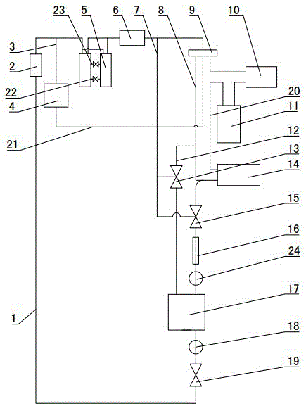
[0033] An air conditioner oil return device, comprising a compressor 5, an oil separator 6, a four-way valve 9, a condenser 10 and an evaporator 14, the oil separator 6 is arranged between the compressor 5 and the condenser 10, and the evaporator 14 The refrigerant outlet communicates with the four-way valve 9 through the air return pipe 8, and the refrigerant inlet of the compressor 5 communicates with the four-way valve 9 through the suction pipe, and also includes an oil reservoir 17, and the oil inlet of the oil reservoir 17 is connected to the reversing unit in series. The upper air return pipe 8 communicates with the return air pipe 8 and keeps a normally open state. The pipeline between the refrigerant outlet of the oil separator 6 and the refrigerant outlet of the evaporator 14 communicates with the re...


PUM


Abstract

The invention provides an air conditioner oil returning device, and belongs to the technical field of air conditioners. The air conditioner oil returning device is characterized by further comprising an oil storage device (17), wherein an oil inlet of the oil storage device (17) is serially connected with a reversing unit and then communicates with an air returning tube (8) above the oil inlet of the oil storage device (17); the oil inlet of the oil storage device (17) and the air returning tube (8) are in a normally open state; a pipeline between a refrigerant outlet of an oil separator (6) and a refrigerant outlet of an evaporator (14) communicates with the reversing unit through a compression tube (7); the pipeline and the oil storage device (17) are in a normally closed state; an oil outlet of the oil storage device (17) communicates with an air suction tube through an oil returning tube (1); and the reversing unit is connected with a control system. Lubricating oil can be stored in the oil storage device of the air conditioner oil returning device, so that all oil returning elbows of the air returning tube are omitted, air returning is smooth, refrigerating capacity and energy efficiency ratio are increased, the circumstance that a compressor which is lack of lubricating oil is burnt down in a working process can be avoided, and the service life is long.

Description

technical field [0001] An air conditioner oil return device belongs to the technical field of air conditioners. Background technique [0002] When the multi-connected air conditioning system is running, part of the lubricating oil will be discharged from the compressor together with the refrigerant and enter the system. Only when the lubricating oil discharged into the system can return to the compressor and maintain the dynamic balance of the lubricating oil in the compressor, can the compressor not run smoothly. Lack of oil, otherwise the oil level will drop and the compressor will be short of oil, which will cause the compressor to burn out. Therefore, the moving oil storage volume is the most basic condition to ensure the reliable operation of the compressor. Only when the oil storage volume exceeds the minimum amount required, can the safe and reliable movement of the compressor be guaranteed. [0003] The factors that affect the oil storage capacity of the compressor ...

Claims


Application Information

Patent Timeline
IPC IPC(8): F25B43/00F25B31/00F25B41/04F25B49/02F25B41/20
CPCF25B31/002F25B43/006F25B49/022F25B2600/01F25B41/20
Inventor 相宝军
Owner 相宝军
Why Eureka
Try Eureka