Eureka AIR delivers breakthrough ideas for toughest innovation challenges, trusted by R&D personnel around the world.

Wireless passive real-time temperature measuring sensing apparatus, system, and method for cable joint

A cable joint and sensing device technology, applied in the field of power equipment, can solve the problems of large difference between the temperature value and the actual temperature value, frequent battery replacement, high temperature resistance, etc., to achieve accurate measured temperature value and avoid weak signal transmission. , to avoid the effect of false temperature

Inactive Publication Date: 2016-10-12
廊坊芳远新合电气股份有限公司 +1
View PDF12 Cites 12 Cited by
  • Summary
  • Abstract
  • Description
  • Claims
  • Application Information

AI Technical Summary

Problems solved by technology

Therefore, if you want to avoid and reduce the occurrence of safety accidents, it is mainly to know the temperature change and temperature value of the connection point in advance. However, the existing temperature measurement methods, whether it is active wired non-contact or passive wired contact There are many problems
For example, when measuring temperature, the sensor is disturbed by the surrounding environment and electromagnetic field, the temperature measuring device is large, the sensor is fragile and easy to break, the installation is complicated, the maintenance is difficult, it is not resistant to high temperature, the insulation performance is poor, and it is easy to generate false alarms at high temperature. The difference between the temperature value and the actual temperature value is relatively large, the battery is replaced frequently, and the service life is short.

Method used


Image

  • Wireless passive real-time temperature measuring sensing apparatus, system, and method for cable joint
  • Wireless passive real-time temperature measuring sensing apparatus, system, and method for cable joint
  • Wireless passive real-time temperature measuring sensing apparatus, system, and method for cable joint

Examples


Embodiment 1

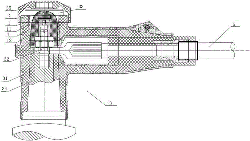
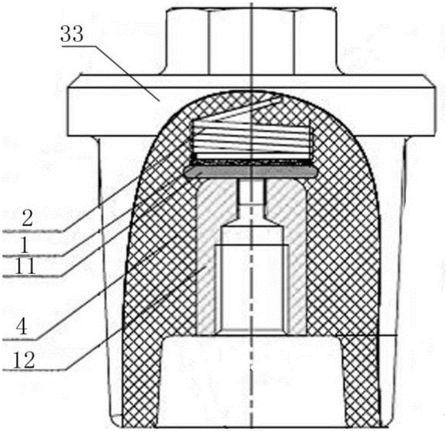
[0041] Such as figure 1 with figure 2 As shown, a cable joint wireless passive real-time temperature measurement sensor device in this embodiment includes a temperature sensor 1 and an antenna 2, and the temperature sensor 1 and the antenna 2 are embedded in the place through an epoxy resin 4 injection curing molding process. In the cable joint 3, the temperature sensor 1 is in contact with the wires in the cable joint 3, and the antenna 2 is fixed on the temperature sensor 1 and communicated with it. The cable joint 3 is connected to one end of the cable 5 and conducts with the wires in the cable 5 .

[0042] In the embodiment of the present invention, the temperature sensor and the antenna are embedded in the cable joint through the epoxy resin injection curing molding process, so that the temperature sensor is in contact with the wire in the cable joint, that is, the temperature sensor is directly in contact with the high-voltage end of the cable joint, and the temperatur...

Embodiment 2

[0053] A kind of temperature sensing system of the present embodiment comprises:

[0054] The temperature collector is used to send temperature acquisition signals, and is also used to receive and send temperature signals;

[0055] The temperature measuring and sensing device as described in Embodiment 1 is used to receive and process the temperature acquisition signal, obtain a temperature signal and send the temperature signal to the temperature collector;

[0056] The terminal device is used to receive and display the temperature signal sent by the temperature collector.

[0057] Every temperature response time T, the terminal device is also used to control the temperature sensor to send a temperature collection signal, and within the preset time after the temperature sensor sends the temperature collection signal, the terminal device does not receive the temperature signal, the terminal equipment sends out an alarm signal.

[0058] The terminal device is also used to com...

Embodiment 3

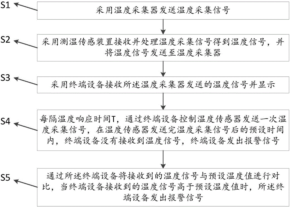
[0063] Such as image 3 As shown, a temperature sensing method of the present embodiment includes the following steps:

[0064] Step S1, using a temperature collector to send a temperature acquisition signal;

[0065] Step S2, using the temperature sensing device as described in Embodiment 1 to receive and process the temperature acquisition signal, obtain a temperature signal and send the temperature signal to the temperature collector;

[0066] Step S3, using a terminal device to receive and display the temperature signal sent by the temperature collector.

[0067] Step S4, every temperature response time T, the terminal device controls the temperature sensor to send a temperature collection signal, and the terminal device does not receive the temperature collection signal within a preset time after the temperature sensor sends the temperature collection signal. temperature signal, the terminal equipment sends out an alarm signal;

[0068] In step S5, the terminal device ...


PUM


Abstract

The invention relates to a wireless passive real-time temperature measuring sensing apparatus, system, and method for a cable joint. The apparatus comprises a temperature sensor and an antenna that are buried into a cable joint by an epoxy resin injection curing molding process. The temperature sensor is in contact with a wire in the cable joint; and the antenna is fixed on the temperature sensor and is communication connection with the temperature sensor. According to the invention, because the temperature sensor and the antenna are buried into the cable joint by the epoxy resin injection curing molding process and the temperature sensor is in contact with the high-voltage end of the cable joint directly, the temperature sensor can measure the temperature of the high-voltage end of the cable joint effectively and accurately, so that a problem of inaccurate temperature measurement due to temperature differential complementing can be solved. The temperature sensor is buried into the cable joint by the epoxy resin injection curing molding process, post maintenance is avoided; and with the antenna, a problem of weak signal transmission of the temperature sensor because of thick epoxy resin can be solved.

Description

technical field [0001] The invention relates to the technical field of power equipment, in particular to a device and method for real-time monitoring of the temperature of a conductor inside a power cable joint through a wireless passive contact method. Background technique [0002] Most of the safety accidents in the power distribution industry of my country's power system are caused by the heating of the connection points in the cabinet. Therefore, if you want to avoid and reduce the occurrence of safety accidents, it is mainly to know the temperature change and temperature value of the connection point in advance. However, the existing temperature measurement methods, whether it is active wired non-contact or passive wired contact There are many problems in the formula. For example, when measuring temperature, the sensor is disturbed by the surrounding environment and electromagnetic field, the temperature measuring device is large, the sensor is fragile and easy to brea...

Claims


Application Information

Patent Timeline
IPC IPC(8): G01K1/02G01K13/00G01K1/024
CPCG01K1/024G01K13/00
Inventor 张玉龙王建新张淑琴
Owner 廊坊芳远新合电气股份有限公司
Why Eureka
Eureka Blog
Learn More