Supercharge Your Innovation With Domain-Expert AI Agents!

LED brightness test adjustment device and system

A technology for adjusting devices and brightness, which is applied in measuring devices, testing optical properties, and testing individual semiconductor devices. It can solve problems such as gear switching errors, decreased test accuracy, and limited adjustment gears, achieving high accuracy and improving efficiency. Effect

Active Publication Date: 2016-10-12
SHENZHEN SIDEA SEMICON EQUIP
View PDF10 Cites 1 Cited by
  • Summary
  • Abstract
  • Description
  • Claims
  • Application Information

AI Technical Summary

Problems solved by technology

Different gears need to be manually switched by the tester, which is prone to gear switching errors, and the position of the integrating sphere and optical fiber changes due to the influence of external forces during the switching process, which eventually leads to a decrease in test consistency, or even errors, which affect the test effect
[0003] like figure 1 and figure 2 As shown, a commonly used manual adjustment device structure now includes an integrating sphere part and a brightness adjusting part. The integrating sphere part includes an integrating sphere lower shell 11, an integrating sphere upper shell 12, and a light blocking sheet 13, wherein the integrating sphere upper and lower shell parts The inside is a spherical cavity, and the light blocking sheet is located inside the sphere, and the inside of the cavity is sprayed with a reflective layer. The brightness adjustment part includes a base 21, a light shielding plate 22, an attenuation sheet 23, and a lens 24 (connected with an optical fiber, and the light of the optical fiber enters from the lens 24 and Through the attenuation sheet 23) and the cover plate 25, the attenuation sheet 23 has different specifications, and the attenuation sheets of different specifications can be switched by manually pushing the position of the shading plate to meet the test requirements of different products. Due to the limitation of size, the number of attenuation sheets is generally There are 3, and the adjustment gears are limited, and it is easy to be affected by external factors when adjusting the gears, such as the change of the optical fiber angle due to the influence of external forces, etc., which will cause the test accuracy to drop

Method used


Image

  • LED brightness test adjustment device and system
  • LED brightness test adjustment device and system
  • LED brightness test adjustment device and system

Examples


Embodiment Construction

[0027] The preferred embodiments of the invention will be further described in detail below.

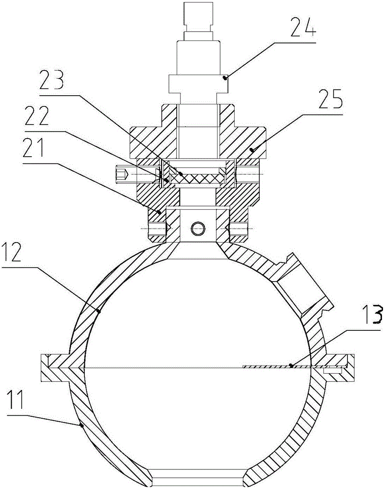
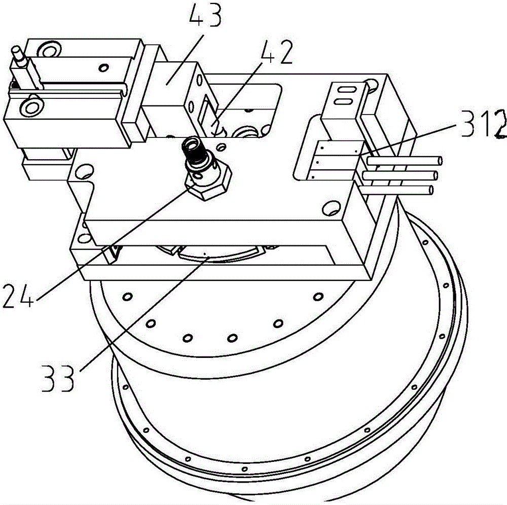
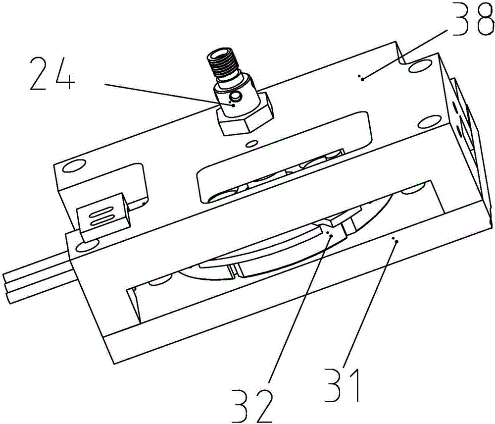
[0028] Such as Figures 1 to 9 As shown, an embodiment of the LED brightness test adjustment device includes: a drive assembly, a light attenuating sheet mount 32, a sensor 312, and a plurality of light attenuating sheets 37 with different degrees of light attenuation. The light attenuating sheet mount 32 The corresponding light-attenuating sheet 37 is installed in different positions (the light-attenuating sheet mounting seat 32 can be provided with a light-attenuating sheet hole, and the light-attenuating sheet 37 is installed in the light-attenuating sheet hole), that is to say, each different light-attenuating sheet 37 and The different positions of the light attenuating sheet mounting base 32 correspond one to one.

[0029] When working, the driving assembly drives the light attenuating sheet mounting seat 32 to rotate, and the rotation of the light attenuating sheet mounting s...


PUM


Abstract

The invention discloses an LED brightness test adjustment device and system. The device comprises a driving assembly, an optical attenuation sheet installation base, a sensor and a plurality of optical attenuation sheets having different light attenuation degrees. The optical attenuation sheets are arranged at different places of the optical attenuation sheet installation base correspondingly; the driving assembly is used for driving the optical attenuation sheet installation base to rotate, and the optical attenuation sheet installation base drives the optical attenuation sheets to move to a set light passing place; and the sensor is used for detecting the current position of the optical attenuation sheet installation base to judge the current optical attenuation sheet located in the light passing place. The device and method improve efficiency of adjusting attenuation degree of the light entering an integrating sphere, and are high in accuracy.

Description

【Technical field】 [0001] The invention relates to the field of LED testing, in particular to an LED brightness testing and adjusting device and system. 【Background technique】 [0002] The current LED testing machine needs to use a spectrometer to test various optical parameters of the chip during the process of testing the chip. Due to the different specifications of LED chips, in order to make the testing machine compatible with various chip tests, it is necessary to attenuate the light with different brightness so that the attenuated light is within the normal range of the test. At this stage, the manual push-pull method is usually used to change different attenuation gears to adapt to the testing of core particles with different specifications. Different gears need to be switched manually by the tester, which is prone to gear switching errors, and the position of the integrating sphere and optical fiber changes due to the influence of external forces during the switching...

Claims


Application Information

Patent Timeline
Patent Type & Authority Applications(China)
IPC IPC(8): G01M11/02G01R31/26
CPCG01M11/02G01R31/2601
Inventor 沈杰王业文栗巍王胜利胡泓
Owner SHENZHEN SIDEA SEMICON EQUIP
Features
  • R&D
  • Intellectual Property
  • Life Sciences
  • Materials
  • Tech Scout
  • Unparalleled Data Quality
  • Higher Quality Content
  • 60% Fewer Hallucinations
Learn More