Pedal unit testing system and control method thereof

A technology for unit testing and control methods, applied in vehicle testing, machine/structural component testing, measuring devices, etc., to solve problems such as low testing efficiency and inconvenient placement of sensors

Inactive Publication Date: 2016-10-12
CHONGQING UNIV
View PDF7 Cites 11 Cited by
  • Summary
  • Abstract
  • Description
  • Claims
  • Application Information

AI Technical Summary

Problems solved by technology

In the existing production line, the method of measuring the rotation angle of the pedal is generally to use an angle sensor, a rotary potentiometer or a displacement sensor to measure, but this detection method is not efficient in the production line, and the placement of the sensor is inconvenient. The invention can realize the measurement of the rotation angle and displacement of the automobile pedal without any displacement sensor and angle sensor

Method used


Image

  • Pedal unit testing system and control method thereof
  • Pedal unit testing system and control method thereof
  • Pedal unit testing system and control method thereof

Examples


Embodiment Construction

[0068] The present invention will be further described below in conjunction with the accompanying drawings and embodiments.

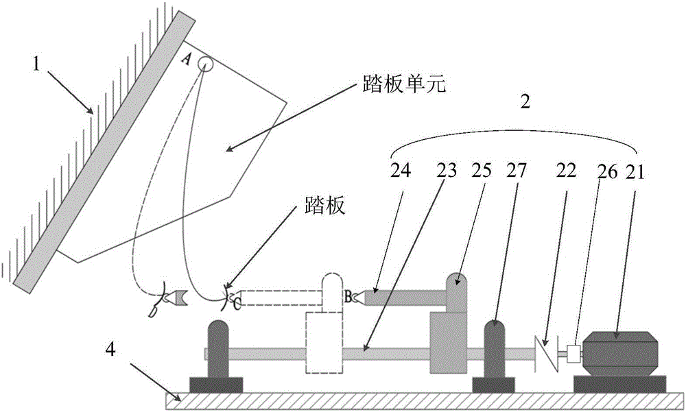
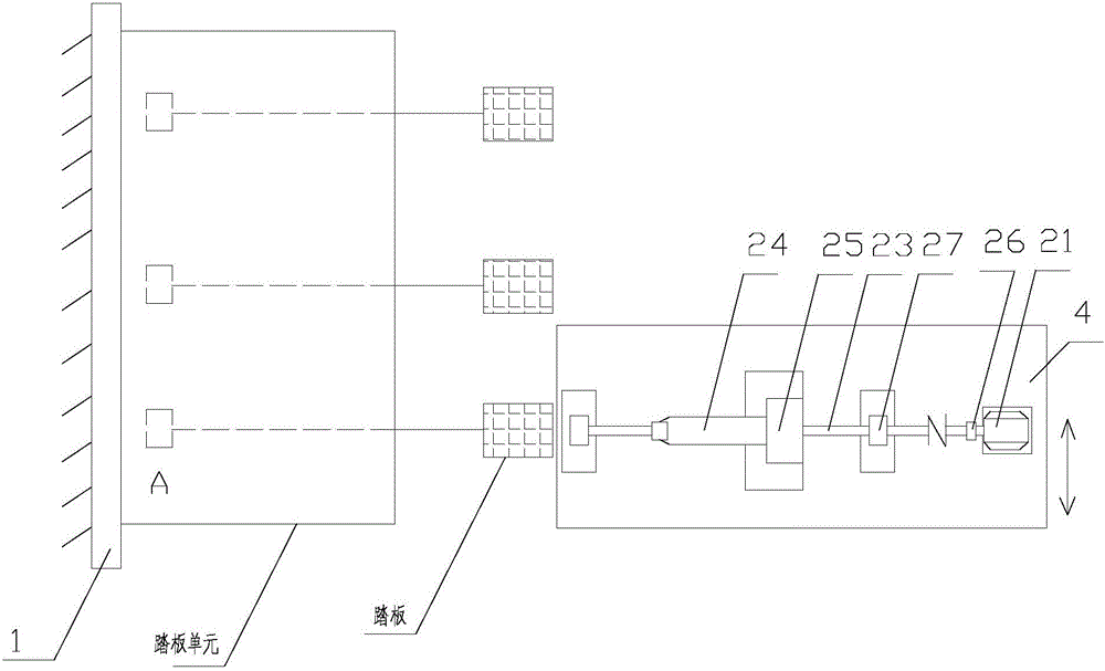
[0069] Such as Figure 1-Figure 6 As shown, a pedal unit testing system includes a fixture 1, a pedal detection mechanism 2, and a data processing device;

[0070] The clamp 1 is used to fix the pedal unit;

[0071] The pedal detection mechanism 2 includes a servo motor 21, the servo motor 21 drives the screw mandrel 23 to rotate through the shaft coupling 22, the screw mandrel 23 drives the test push rod 24 to advance and retreat, and the test push rod 24 pushes the pedal of the pedal unit to rotate;

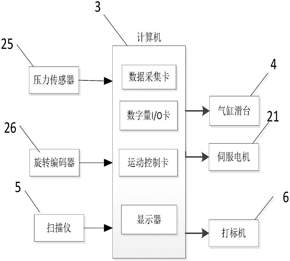
[0072] The test push rod 24 is provided with a pressure sensor 25, and the pressure sensor 25 is used to detect the resistance of the pedal; the output shaft of the servo motor 21 is provided with a rotary encoder 26, and the rotary encoder 26 is used to detect the resistance of the test push rod. Displacement of rod 24;

[0073] The rotary encoder 26...


PUM


Abstract

The invention discloses a pedal unit testing system and a control method thereof. The system comprises a clamp and a pedal detection mechanism; a pedal unit is fixed by the clamp; the pedal detection mechanism comprises a servo motor, the servo motor drives a screw to rotate, the screw drives a testing push rod to move forwards or backwards, and the testing push rod pushes a pedal of the pedal unit to rotate; the testing push rod is provided with a pressure sensor, and the pressure sensor is used to detect the resistance of the pedal; an output shaft of the servo motor is provided with a rotation encoder, and the rotation encoder is used to detect displacement of the testing push rod; and the servo motor, the pressure sensor and the rotation encoder are all connected to a data processor, and the data processor reads output data of the pressure sensor and the rotation encoder and combines a screw lead with a pedal fixation parameter to calculate and output the rotation angle and resistance data of the pedal. According to the invention, the rotation angle and resistance of the pedal can be measured accurately and efficiently, and a test process is controlled by software and runs automatically.

Description

technical field [0001] The invention relates to the technical field of automobile engineering testing, and mainly relates to a pedal unit testing system and a control method thereof. Background technique [0002] The car pedal unit consists of pedal box, accelerator pedal, brake pedal, clutch pedal, off-master cylinder, foot brake valve and other components. Whether the pedal unit product meets the technical requirements directly affects the safety and stability of the car. The present invention is mainly aimed at the resistance during the rotation of the accelerator pedal, brake pedal and clutch pedal in the pedal unit, and when the resistance reaches the maximum value, the pedal turns over. angle measurement. In the existing production line, the method of measuring the rotation angle of the pedal is generally to use an angle sensor, a rotary potentiometer or a displacement sensor to measure, but this detection method is not efficient in the production line, and the placem...

Claims


Application Information

Patent Timeline
Patent Type & Authority Applications(China)
IPC IPC(8): G01M17/007
CPCG01M17/007
Inventor 刘小峰曾柯
Owner CHONGQING UNIV
Why Eureka
Try Eureka