
A near-eye display system, virtual reality equipment and augmented reality equipment

A near-eye display and concave mirror technology, which is applied in mechanical mode conversion, computer parts, graphics reading, etc., can solve the problems of increasing the field of view of virtual reality technology and augmented reality technology, and the inability to experience users' augmented reality, so as to avoid adjustment The result is inaccurate, the effect of expanding the applicable population and clear visual experience

Active Publication Date: 2019-04-30
CHENGDU IDEALSEE TECH
View PDF7 Cites 1 Cited by
  • Summary
  • Abstract
  • Description
  • Claims
  • Application Information

AI Technical Summary

Problems solved by technology

[0006] The purpose of the present invention is to provide a near-eye display system, a virtual reality device and an augmented reality device, which solves the problem in the prior art that the augmented reality device has strict restrictions on the position observed by the human eye, resulting in the inability to provide users with a good The technical problems of augmented reality experience increase the field of view provided by virtual reality technology or augmented reality technology, so that virtual reality technology or augmented reality technology can visually meet the viewing needs of human eyes, thereby providing users with immersive to experience

Method used


Image

  • A near-eye display system, virtual reality equipment and augmented reality equipment
  • A near-eye display system, virtual reality equipment and augmented reality equipment
  • A near-eye display system, virtual reality equipment and augmented reality equipment

Examples


Embodiment Construction

[0030] The following will clearly and completely describe the technical solutions in the embodiments of the present invention with reference to the accompanying drawings in the embodiments of the present invention. Obviously, the described embodiments are only some, not all, embodiments of the present invention. Based on the embodiments of the present invention, all other embodiments obtained by persons of ordinary skill in the art without creative efforts fall within the protection scope of the present invention.

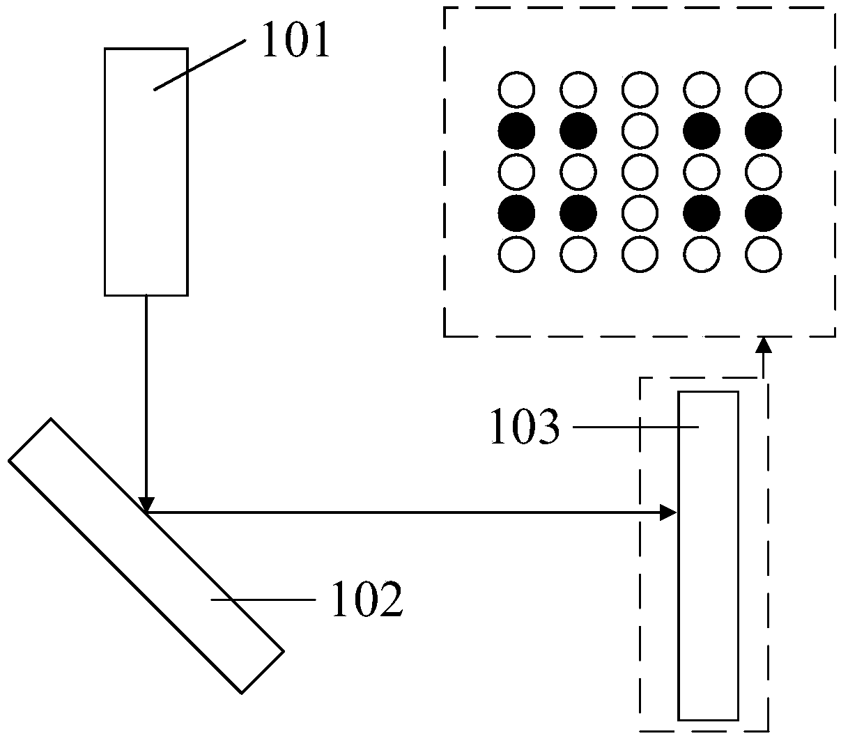
[0031] Before introducing the technical solution in the embodiment of the present invention, first introduce the technical principle of laser scanning imaging, please refer to figure 1 , figure 1 Schematic for laser-scanned retinal imaging, such as figure 1 As shown, 101 is a laser generator, 102 is a two-dimensional scanning device, and 103 is a retina of a human eye.

[0032] For the convenience of introduction, take the imaging image with a resolution of 5*5 a...


PUM


Abstract

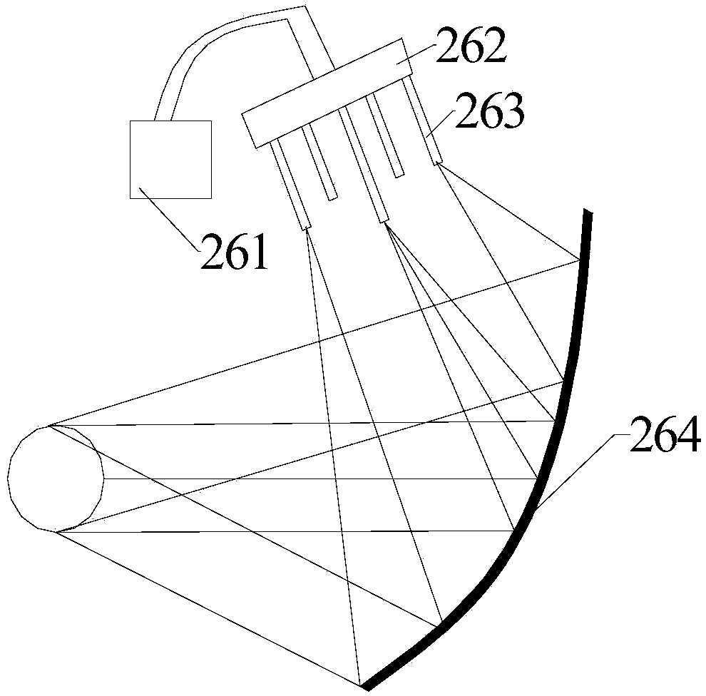
Provided are a near-eye display system, virtual-reality device, and augmented-reality device. A near-eye display system comprises a laser light source (261), a beam-splitting component (262), a scanning optical-fiber array (263), and a first concave reflector (264); the beam-splitting component (262) comprises a number M*N of output terminals; each output terminal is provided with an optical switch; the scanning optical-fiber array (263) comprises a number M*N of optical fibers; the M*N optical fibers are respectively connected to the M*N output terminals; M and N are positive integers greater than or equal to 2; when passing through the beam-splitting component (262), the laser light emitted by the laser light source (261) is split into M*N light beams; a light beam outputted from the output terminal corresponding to an optical switch in an activated state on the beam-splitting component (262) passes through the scanning optical-fiber array (263), and is then reflected into the human eye by the first concave reflector (264). The light beam outputted by each optical fiber is conical, therefore the width of the light beam increases continuously with an increase in the optical path; thus the exit-pupil diameter of the near-eye display system is increased and the strict limitations on the position of the eye during observation are reduced or avoided.

Description

technical field [0001] The invention relates to the fields of virtual reality and augmented reality, in particular to a near-eye display system, a virtual reality device and an augmented reality device. Background technique [0002] Virtual reality (English: Virtual Reality; abbreviation: VR) is a computer simulation system that can create and experience a virtual world. It uses a computer to generate a simulated environment. Users are immersed in the environment, bringing users a sensory experience beyond the real life environment. In terms of vision, virtual reality technology uses computer equipment to generate images of virtual scenes, and transmits image light to human eyes through optical devices, so that users can fully experience the virtual scene visually. [0003] Augmented reality (English: Augmented Reality; abbreviation: AR) is a technology that uses virtual objects or information to enhance the reality of real scenes. Augmented reality technology is usually b...

Claims


Application Information

Patent Timeline
Patent Type & Authority Patents(China)
IPC IPC(8): G06F3/01
CPCG06F3/01
Inventor 黄琴华周旭东喻秀英
Owner CHENGDU IDEALSEE TECH
Learn More