Low-profile conformal antenna

A technology of conformal antennas and conformal antenna arrays, applied to antennas, slot antennas, antenna components, etc., can solve the problems of large air resistance, high antenna profile, and difficulty in meeting streamlined design, and achieve low air resistance and high buff, effect with simple structure

Inactive Publication Date: 2016-10-12
CHINA ELECTRONIC TECH GRP CORP NO 38 RES INST
View PDF16 Cites 19 Cited by
  • Summary
  • Abstract
  • Description
  • Claims
  • Application Information

AI Technical Summary

Problems solved by technology

The traditional antenna that is directly welded on the carrier shell has a high profile a...

Method used


Image

  • Low-profile conformal antenna
  • Low-profile conformal antenna
  • Low-profile conformal antenna

Examples


Embodiment 1

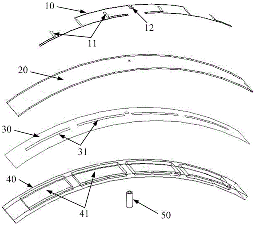
[0036] see figure 1 with figure 2 A low-profile conformal antenna includes a feed network 10, a dielectric substrate 20, a metal sheet 30, and a metal cavity-backed plate 40 that are sequentially layered and fixedly connected; the overall arc-shaped slat of the low-profile conformal antenna The profile height of the low-profile conformal antenna is 1 / 45 wavelength of the center frequency of the low-profile conformal antenna.

[0037] see figure 2 , the feed network 10 is fixed on the outer surface of the dielectric substrate 20 , and the metal sheet 30 is fixed on the inner surface of the dielectric substrate 20 .

[0038] The feed network 10 is a microstrip power divider with equal amplitude and non-equal phase, which is composed of one input terminal and four output terminals, and compensates the phase difference from the non-planar slot array to the equal phase plane;

[0039] Four radiating slits 31 are evenly distributed on the metal sheet 30 to form a slit array, an...

Embodiment 2

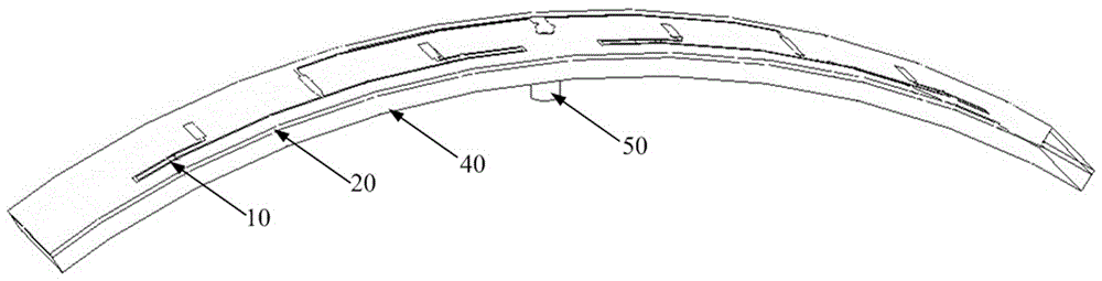
[0043] see image 3 with Figure 4 , the low-profile conformal antenna in Embodiment 2 is an extension of the antenna in Embodiment 1, from the original 4 radiation slots 31 to 8 radiation slots 31 . The radiating slots 31 are still in a straight slot array along the length direction of the metal sheet 30 , and the distance between adjacent radiating slots 31 is equal.

[0044] see Figure 5 , Image 6 with Figure 7 , the feed network 10 is composed of one input terminal and eight output terminals, and the corresponding radiation slots 31 are expanded into 8 slot arrays arranged in a line, and the cavities 41 on the metal back cavity board 40 are also expanded into 8 equally spaced arrays. cavity composition. Other structures are with embodiment 1.

[0045] The profile height of the antenna is 1 / 45 of the wavelength of the center frequency of the low-profile conformal antenna.

[0046] see Figure 8 with Figure 9 , the bandwidth of the port standing wave of the ante...

Embodiment 3

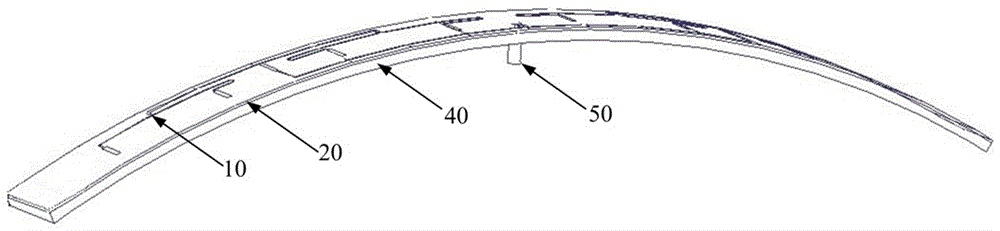
[0048] see Figure 10 , this embodiment is extended from Embodiment 2 to form a one-dimensional phase-swept array. The antenna array is composed of 16 antennas in Embodiment 2. The adjacent metal cavity-backed plates 40 and the dielectric substrate 20 are seamlessly connected, and the coaxial feed connector 50 of each low-profile conformal antenna is located at Same side of the low-profile conformal antenna array. The section height of the low-profile conformal antenna array is 1 / 45 of the center frequency wavelength of the low-profile conformal antenna, and can realize one-dimensional phase scanning.


PUM


Abstract

The invention relates to a low-profile conformal antenna, which comprises a feed network, a dielectric substrate, a metal sheet and a metal back cavity plate which are fixedly connected in a layered manner in sequence. The overall low-profile conformal antenna is in an arc-shaped lath form; the profile height is 1/30-1/50 of wavelength of the center frequency of the low-profile conformal antenna and is much less than those of a waveguide slot antenna and a microstrip patch; and the requirement of a modern carrier on low air resistance is met. The feed network comprises an input end and at least four output ends; at least four radiating slots are evenly distributed in the metal sheet; at least four cavities are evenly distributed on one side surface of the metal back cavity plate; and a coaxial feed joint is arranged at the middle part of the other side surface of the metal back cavity plate. More than two low-profile conformal antennas are connected in parallel to form a low-profile conformal antenna array. The low-profile conformal antenna easily conforms to various carriers, and is simple in structure and convenient to process.

Description

technical field [0001] The invention belongs to the technical field of antennas, in particular to a low profile conformal antenna. Background technique [0002] Antennas are an essential part of wireless communication systems. With the development of science and technology, modern carriers such as aircraft, ships, and satellites have higher and higher requirements for antennas, especially for high-speed aircraft. The weight requirement is particularly strict. The traditional antenna that is directly welded on the carrier shell has a high profile and high air resistance, which is difficult to meet the streamlined design of the modern carrier. Therefore, it is very meaningful to study the antenna conformal to the surface of the carrier, with low profile and miniaturization. [0003] The slot antenna is a common type of antenna that is easy to conform to the carrier. It has the advantages of compact structure and small volume, and is often given priority when designing the an...

Claims


Application Information

Patent Timeline
IPC IPC(8): H01Q1/28H01Q1/38H01Q1/50H01Q13/18
CPCH01Q1/285H01Q1/38H01Q1/50H01Q13/18
Inventor 郭琳强云飞陈嗣乔方正新罗林
Owner CHINA ELECTRONIC TECH GRP CORP NO 38 RES INST
Why Eureka
Try Eureka