
Carbon brush contact conductive device

A conductive device and contact technology, which is applied in the direction of rotating collectors, connections, circuits, etc., can solve the problems of dislocation of the conductive track between the fan and the frame material, the instability of accelerated conduction, and the easy deviation of the conductive wheel, etc., to achieve long service life , good electrical conductivity, easy to replace

Active Publication Date: 2019-01-22
汉狮光动科技(广东)有限公司
View PDF5 Cites 0 Cited by
  • Summary
  • Abstract
  • Description
  • Claims
  • Application Information

AI Technical Summary

Problems solved by technology

However, this kind of conductive device often appears non-conductive, and its non-conductive reasons are various, and the common ones are: the oxidation of the conductive copper sheet and the conductive wheel; the conductive wheel is easy to deviate from the track of the conductive rail; the device of the conductive wheel is installed on the fan material On the other hand, the conductive copper sheet device is installed on the frame material, which causes the gap between the fan and the frame material to be misaligned with the conductive track; in addition, the drop angle after the door and window is installed for a period of time also accelerates the instability of the conduction

Method used


Image

  • Carbon brush contact conductive device
  • Carbon brush contact conductive device
  • Carbon brush contact conductive device

Examples


Embodiment Construction

[0040] The present invention is further described below in conjunction with accompanying drawing and embodiment:

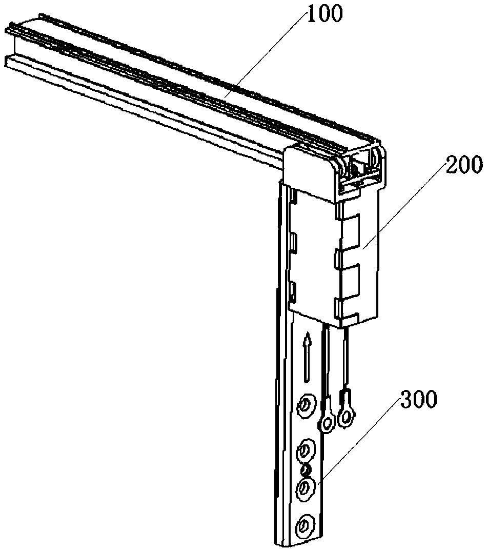
[0041] Such as figure 1 As shown, a carbon brush contact-type conductive device includes a carbon brush device box, a positioning mounting block and a conductive rail. The upper end of the conductive rail is fixed on the profile, and its lower end is connected to the carbon brush device box. , and the positioning mounting block is located inside the carbon brush device box.

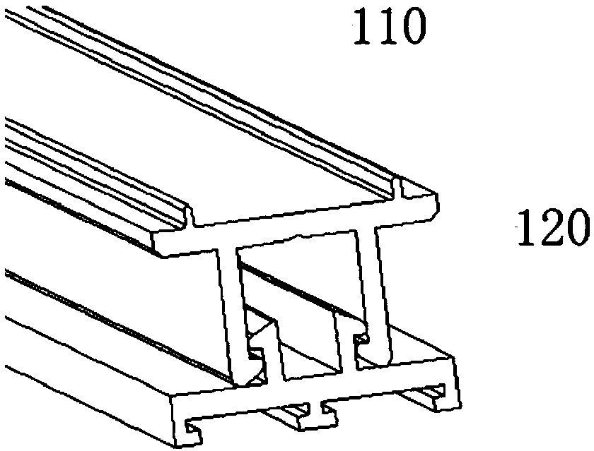
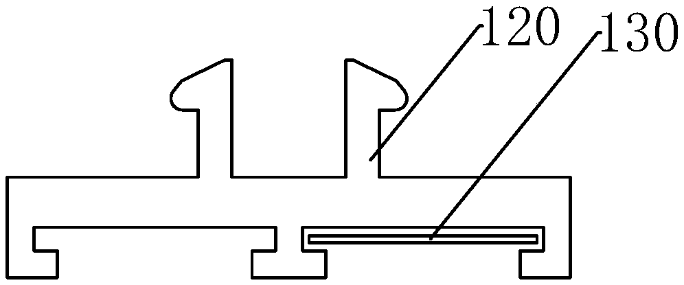
[0042] Such as Figure 2-3 As shown, the conductive rail includes a conductive rail groove and a carbon brush guide rail, the upper end of the conductive rail groove is fixed on the profile, and its lower end is connected with the carbon brush guide rail. Specifically, the groove of the conductive rail is in the shape of π, the lower end of which is provided with a first hook with an inner buckle, and the upper end of the carbon brush guide rail is provided with a second hook that cooperate...


PUM


Abstract

The invention discloses a carbon brush contact type conductive device comprising a carbon brush device box, a positioning installation block, and a conductor rail. The upper end of the conductor rail is fixed on a profile, and the lower end is connected with the carbon brush device box. The top end of the carbon brush device box is connected with the conductor rail through rollers, and the carbon brush device box slides along the conductor rail. A carbon brush made of graphite is arranged inside the carbon brush device box, and a lead at the lower end of the carbon brush is connected with an electric hollow shutter through a terminal. The positioning installation block is arranged at the lower end of the conductor rail, and is fixed to the side of a door-window sash material. Electric conduction is achieved using the carbon brush in the invention. The problem that a shutter conductive device is non-conductive in the prior art is solved. The non-conduction defect of a conductive device is solved from different angles. Moreover, the whole device has a longer service life.

Description

technical field [0001] The invention relates to the technical field of electric louvers, in particular to a device for conducting electricity and controlling electric louvers with a carbon brush contact. Background technique [0002] The insulating glass is driven by a built-in electric blind conductive device. The conductive device has been used since the beginning of the blind, and has gradually developed into a built-in electric blind for sliding windows (doors). The commonly used conduction method is to conduct power supply through conductive contact between the conductive rail of the window (frame) material and the sliding conductive device on the window (fan). The common methods are copper conductive wheels and copper contact blocks. However, this kind of conductive device often appears non-conductive, and its non-conductive reasons are various, and the common ones are: the oxidation of the conductive copper sheet and the conductive wheel; the conductive wheel is easy ...

Claims


Application Information

Patent Timeline
Patent Type & Authority Patents(China)
IPC IPC(8): H01R39/22H01R39/26H01R39/27H01R39/38
CPCH01R39/22H01R39/26H01R39/27H01R39/383H01R2201/10
Inventor 邓扬礼
Owner 汉狮光动科技(广东)有限公司
Learn More