
A Design Method of Photoactive Logic Circuit Based on DNA Double Helix Structure

A technology of double helix structure and logic circuit, applied in the field of DNA nanometer, can solve problems such as the limitation of the number of steps of fluorescence energy transfer

Active Publication Date: 2017-06-30
邦奇(河南)生物技术有限公司
View PDF2 Cites 0 Cited by
  • Summary
  • Abstract
  • Description
  • Claims
  • Application Information

AI Technical Summary

Problems solved by technology

However, affected by the efficiency of fluorescent energy transfer and the type of fluorescent molecules, the number of steps for fluorescent energy transfer is also limited.

Method used


Image

  • A Design Method of Photoactive Logic Circuit Based on DNA Double Helix Structure
  • A Design Method of Photoactive Logic Circuit Based on DNA Double Helix Structure
  • A Design Method of Photoactive Logic Circuit Based on DNA Double Helix Structure

Examples


Embodiment Construction

[0029] A method for designing a photoactive logic circuit based on a DNA double helix structure, the specific steps of the method for designing a photoactive logic circuit are as follows:

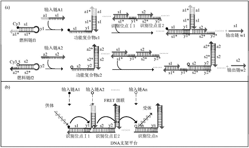
[0030] (1) Based on the photonic circuit design principle of DNA double helix structure, design the input strand, fuel DNA strand and DNA double helix structure required in the reaction;

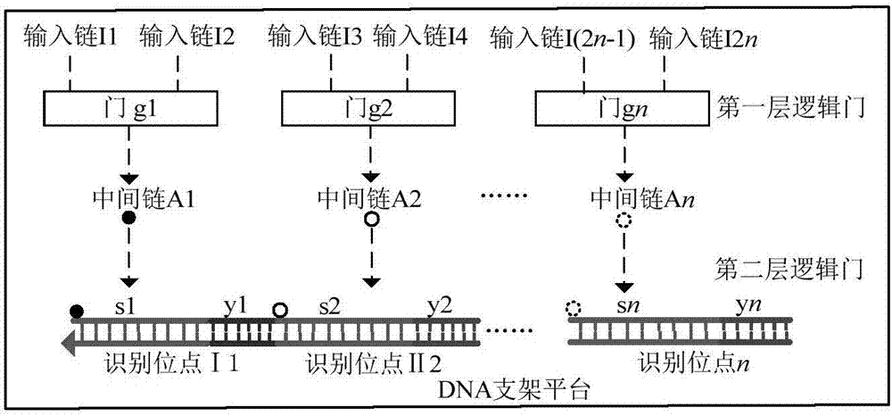
[0031] (2) Coding of the input signal: add the input chain I1 and the input chain I2 to the solution, pass through the logic gate g1, and under the action of the small fulcrum t, the input chain I1 first reacts with the gate complex to produce a gate compound after the initial reaction The material, the input chain I2 and the gate complex after the initial reaction undergo an irreversible chain displacement reaction, so that the reaction proceeds in the positive direction, displacing the intermediate chain A1;

[0032] (3) Transmitting of the photoactive signal: the intermediate chain A1 generated by the ...


PUM


Abstract

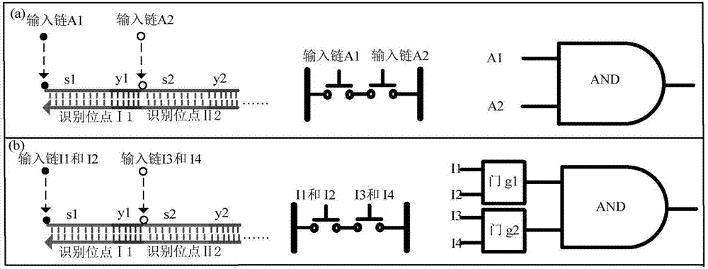
The invention belongs to the field of a DNA nanotechnology, and relates to a design method of a light-activated logic circuit based on a DNA double-helix structure. The application of realizing a biological logic function through partial optical signal transmission is the hot application of a DNA molecule logic circuit. According to the method, the DNA double-helix structure is taken as a bracket platform; a mode of encoding position information of fluorescence molecules by use of two layers of DNA strand displacement reaction is designed; and compared with a single-layer DNA strand displacement encoding mode, the mode provided by the invention has the advantages that under the condition that the numbers of fluorescence molecules are the same, the input signals is doubled. Moreover, through adoption of a fluorescence resonance energy transfer technology, the multifunctional light-activated logic circuit with multi-way input is realized.

Description

technical field [0001] The invention belongs to the field of DNA nanotechnology, and relates to a design method of a photoactive logic circuit based on a DNA double helix structure. Background technique [0002] Biological systems exploit the dynamic interactions between molecules to manage their complex behavioral processes, so the development of technologies to observe and manipulate these molecular interactions is crucial to advance smart imaging and smart therapeutics in vivo. To implement these technological approaches, molecular logic circuits are a useful tool that can control the course of molecular reactions at the molecular level. In conventional design, in order to realize large-scale complex logic circuits, it is often realized by cascading logic gates. Since this kind of circuit relies on the step-by-step reaction of DNA molecules through diffusion in a solution environment, it usually takes a longer calculation time. In contrast, in the control system of livin...

Claims


Application Information

Patent Timeline
Patent Type & Authority Patents(China)
IPC IPC(8): H03K19/20
CPCH03K19/20
Inventor 张勋才宋文军张焕龙顾冬华王华东牛莹孙冬孙军伟申超楠崔光照王延峰
Owner 邦奇(河南)生物技术有限公司
Learn More