Photonic microwave phased array transceiving system and method thereof

A photonic microwave and transceiver system technology, applied in the field of microwave photonics, can solve the problems of difficult and unrealistic changes in the delay distribution of single-channel delay adjustment, and achieve adjustability and reconfigurability, high cost performance and high cost performance. reliability effect

Active Publication Date: 2016-10-12
YANGZHOU UNIV
View PDF13 Cites 10 Cited by
  • Summary
  • Abstract
  • Description
  • Claims
  • Application Information

AI Technical Summary

Problems solved by technology

However, for a microwave phased array system with a large number of antenna elements, there are still many technical difficulties in realizing a reconfigurable and adjustable real-time photon delay distribution of microwave signal transmission and reception ([6]E.I.Ackerman, C.H.Cox, "Optimization of photonic transmit/receive module performance," Microwave Photonics, 2009. MWP'09. International Topical Meeting on, pp.1-4, 2009. [7] M.Shen and R.A.Minasian, "Linearization Processing of a Novel Short Time-Delay WDM Superposed FibreBragg Grating,” IEEE Photonics Technology Lette

Method used


Image

  • Photonic microwave phased array transceiving system and method thereof
  • Photonic microwave phased array transceiving system and method thereof
  • Photonic microwave phased array transceiving system and method thereof

Examples


Embodiment

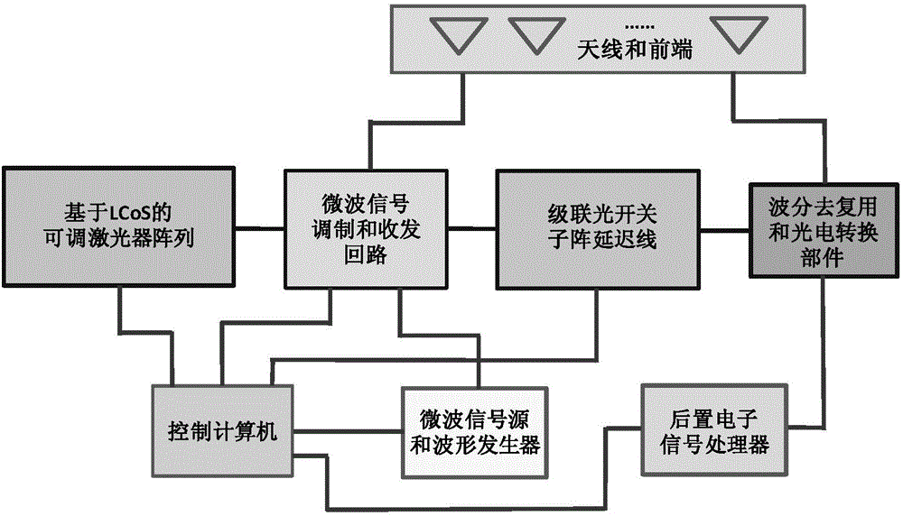
[0034] The following takes a microwave phased array transceiver system with 256 antenna units as an example to describe in detail. 16 LCoSs are used to execute the real-time delay signal processing of sending and receiving of the whole system. Each LCoS executes and processes 16 optical signals corresponding to 16 antenna units and completes the functions of wavelength selection and output coupling control of these optical signals. The 16 signal delays processed by each LCoS are used as unit delays in a sub-array, so there are 16 sub-arrays in total. Such a combination structure completes all delay amounts and delay distributions required by 256 element antennas.

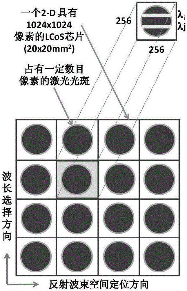
[0035] Such as figure 2 As shown, the photonic microwave phased array transceiver system of the present invention adopts a two-dimensional LCoS with a large number of pixels (that is, a liquid crystal unit under a distributed voltage), and performs 16 active pixel planes of LCoS with 1024 or more pixels on each si...


PUM


Abstract

The invention discloses a photonic microwave phased array transceiving system and method thereof. On the basis of an LCoS tunable laser array, multi-channel wavelength tunable laser is generated; after a microwave signal of an electrooptical modulator is modulated and the unit delay is obtained through a high-dispersion optical fibre, a sub-array delay line of a cascade optical switch is input; distribution of multi-channel retardation is obtained; the multi-channel retardation is transmitted to an optical detector; an output signal of the optical detector enters an electronic signal processor to perform electronic signal processing, such that processing of a received loop signal is realized; a delayed modulated optical signal is input into a wavelength division demultiplexing and photoelectric conversion part; an antenna unit transmits a signal through an electric circulator; and thus, processing of a sent loop signal is realized. According to the photonic microwave phased array transceiving system and method thereof disclosed by the invention, a lot of reconfigurable and adjustable real-time delay can be generated through a photonic technology; furthermore, the photonic microwave phased array transceiving system and method thereof are used in delay signal processing of sending and receiving channels of a microwave phased array; therefore, pointing control of transmitting beams is realized; and received signal processing of obtained target information is realized.

Description

technical field [0001] The invention belongs to the field of microwave photonics technology, in particular to a photon microwave phased array transceiver system and a method thereof. Background technique [0002] In the middle of the twentieth century, people started the technical revolution of replacing mechanical rotating antennas with phased array antennas. On the one hand, phased arrays have high performance and wide application advantages. Today, phased array systems have been fully applied in defense and civilian fields such as radar, communications, electronic warfare, and navigation. On the other hand, as the requirements from applications continue to improve the performance of phased array antenna systems, if today's microwave engineering hardware and systems only use electronic technology, they cannot meet the ever-increasing requirements due to their limited signal response speed and bandwidth. ([1]Hunter D.B., Minasian R.A., "Photonic signal processing of micro...

Claims


Application Information

Patent Timeline
IPC IPC(8): H04B7/06H04B7/08H04B10/50H04B10/572
CPCH04B7/0667H04B7/0828H04B10/503H04B10/572
Inventor 沈明亚
Owner YANGZHOU UNIV
Why Eureka
Try Eureka