Box and ball linkage control method and device aiming at rotating mirror holder, as well as electronic equipment

A linkage control, gun ball technology, applied in the direction of TV, electrical components, color TV, etc., can solve the problem of low monitoring quality and achieve the effect of rapid adjustment

Active Publication Date: 2016-10-12
BEIJING DEEPGLINT INFORMATION TECH
View PDF7 Cites 12 Cited by
  • Summary
  • Abstract
  • Description
  • Claims
  • Application Information

AI Technical Summary

Problems solved by technology

[0004] The embodiment of the present application proposes a method, device and electronic equipment for the gun-ball linkage control of the rotating mirror pan / tilt, so as to overcome the deficiency in the prior art that the monitoring quality of large-area or long-distance monitoring scenes is not high

Method used


Image

  • Box and ball linkage control method and device aiming at rotating mirror holder, as well as electronic equipment
  • Box and ball linkage control method and device aiming at rotating mirror holder, as well as electronic equipment
  • Box and ball linkage control method and device aiming at rotating mirror holder, as well as electronic equipment

Examples


Embodiment 1

[0070] In the first embodiment, the implementation of the method for gun-ball linkage control is described, and now the implementation of the monitoring device control method is described in conjunction with specific scenarios.

[0071] For example, the monitoring device is a gun-ball linkage system, and the gun-ball linkage system is set in a shopping mall to perform monitoring tasks. In this application scenario, the method for implementing the monitoring device control provided by this application may be as follows:

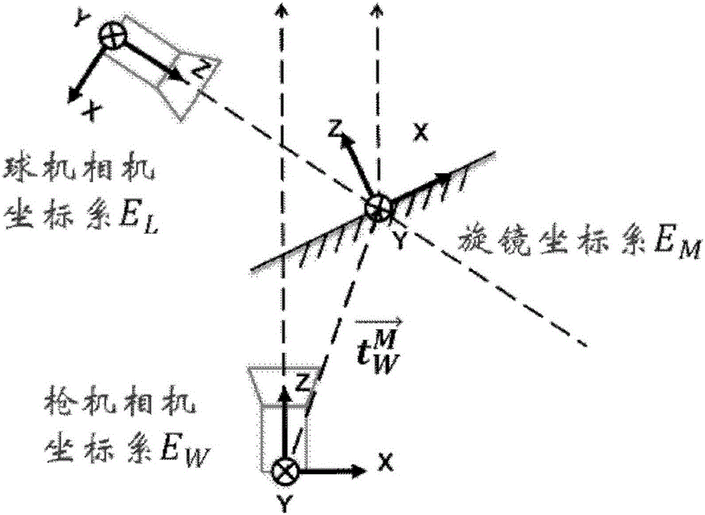
[0072] image 3 It is an exploded schematic diagram of mirror drive in the method of gun-ball linkage control provided in Embodiment 1 of the present application, as shown in image 3 as shown,

[0073] (1) Calculate the initial position of the mirror relative to the world coordinate system E by measuring W The rotation matrix of

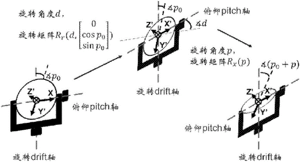
[0074] (2) Assume that the horizontal angle and pitch angle of the mirror relative to the initial position are d 0 and p 0...

Embodiment 3

[0079] Based on the same application concept, the embodiment of the present application also provides a device for the gun-ball linkage control of the rotating mirror head. Since the problem-solving principle of the device is similar to the method for the gun-ball linkage control of the rotating mirror head, this For the implementation of the device, reference may be made to the implementation of the method, and repeated descriptions will not be repeated.

[0080] Figure 4 It is a schematic diagram of the structure of the gun-ball linkage control device provided in Embodiment 3 of the present application, as shown in Figure 4 As shown, the device for the gun-ball linkage control may include:

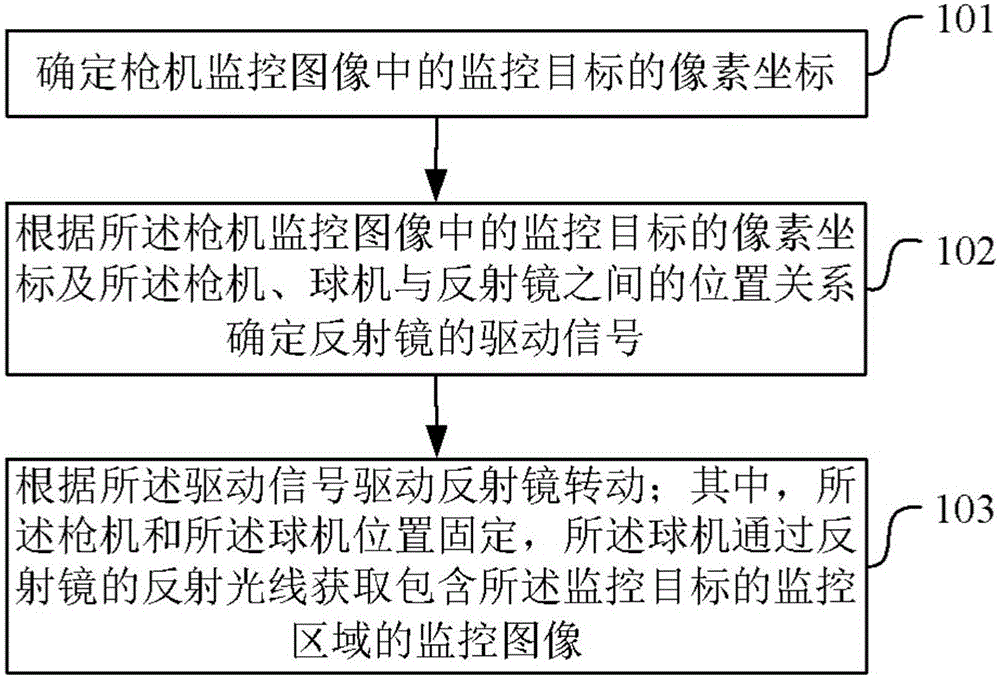
[0081] The first determining unit 401 is configured to determine the pixel coordinates of the monitoring target in the bolt monitoring image;

[0082] The second determination unit 402 is configured to determine the driving signal of the reflector according to the pixel coordinates o...

Embodiment 4

[0102] Figure 5 It is a schematic structural diagram of the electronic device provided in Embodiment 4 of the present application, such as Figure 5 As shown, the electronic equipment for the gun-ball linkage control may include: a processor, a memory, a communication interface and a bus;

[0103] The processor, the memory, and the communication interface are connected through the bus and complete mutual communication;

[0104] The memory stores executable program code;

[0105] The processor executes the program corresponding to the executable program code by reading the executable program code stored in the memory, so as to execute the method for the gun-ball linkage control of the rotating mirror head;

[0106] The communication interface is used to receive the result after the processor executes the program, and send the result;

[0107] Wherein, the method for the gun-ball linkage control of the rotating mirror head includes:

[0108] Determine the pixel coordinates ...


PUM


Abstract

The invention provides a box and ball linkage control method and device aiming at a rotating mirror holder, as well as electronic equipment. The method comprises the steps of: determining a pixel coordinate of a monitored target in an image monitored by a box camera; determining a ball camera according to the pixel coordinate of the monitored target in the image monitored by the box camera to acquire a rotation adjustment amount of the monitored image including the monitored target; determining a driving signal of a reflecting mirror according to the rotation adjustment amount; and driving the reflecting mirror to rotate according to the driving signal, wherein positions of the box camera and the ball camera are fixed, and the ball camera acquires the monitored image including the monitored target in a monitored area according to reflected light of the reflecting mirror. Through adoption of the technical scheme of the invention, driving control can be quickly responded to realize quick adjustment of a monitoring field of the ball camera, so that the monitored target can be better tracked.

Description

technical field [0001] The present application relates to the field of monitoring technology, and in particular to a method, device and electronic equipment for the gun-ball linkage control of the rotating mirror pan / tilt. Background technique [0002] The bolt in the existing gun-ball linkage system is usually a fixed wide-angle camera, and the ball camera is driven by two mutually perpendicular motors to rotate, and the adjustment of the monitoring field of view of the ball camera is realized by directly driving the ball camera to rotate. [0003] For the existing bolt-machine linkage scheme, when the mass of the dome camera is large, the response time of the dome camera rotation will be affected due to inertial factors, and it is impossible to quickly adjust the monitoring field of view of the dome camera to track the monitoring target. Contents of the invention [0004] The embodiment of the present application proposes a method, device and electronic equipment for the...

Claims


Application Information

Patent Timeline
Patent Type & Authority Applications(China)
IPC IPC(8): H04N5/232
CPCH04N23/66H04N23/69
Inventor 胡彬
Owner BEIJING DEEPGLINT INFORMATION TECH
Why Eureka
Try Eureka