Hay cutting crusher

A crusher and hay cutting technology, applied in agricultural machinery and tools, cutting equipment, applications, etc., can solve the problems of reducing feed processing efficiency, reducing input speed, poor forage fineness, etc., to improve feed processing efficiency, The effect of prolonging the service life and improving the fineness

Inactive Publication Date: 2016-10-19
范嘉丽
View PDF5 Cites 3 Cited by
  • Summary
  • Abstract
  • Description
  • Claims
  • Application Information

AI Technical Summary

Problems solved by technology

[0002] With the development of animal husbandry, animal husbandry has higher and higher requirements for forage processing quality. Commonly used forage processing equipment mainly includes hay cutters and pulverizers, of which the hay cutters in the prior art are only It can cut crops such as grass or straw into small pieces, but cannot further crush each small piece, so the fineness of the processed forage is poor, and the livestock are unwilling to eat it. Usually, follow-up processing is required to improve the fineness of the feed. This not only wastes manpower and material resources, but also greatly reduces the feed processing efficiency. In addition, although there is a speed change mechanism in the prior art hay cutter, the speed change mechanism is only used to reduce the input speed, and cannot accurately set the rotation speed gear.

Method used


Image

  • Hay cutting crusher
  • Hay cutting crusher
  • Hay cutting crusher

Examples


Embodiment Construction

[0051] The present invention will be described in further detail below in conjunction with the accompanying drawings.

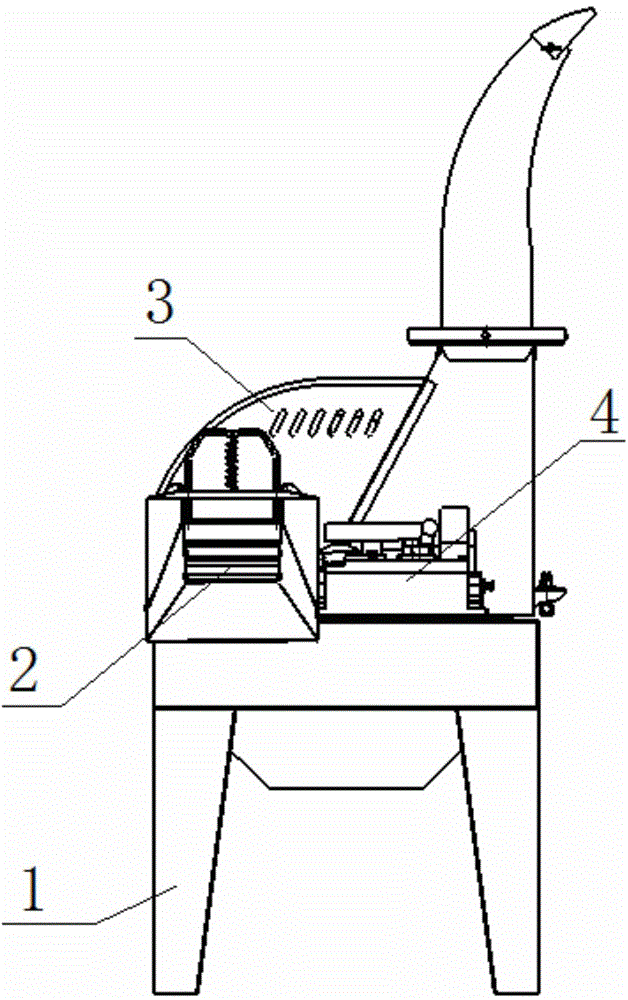
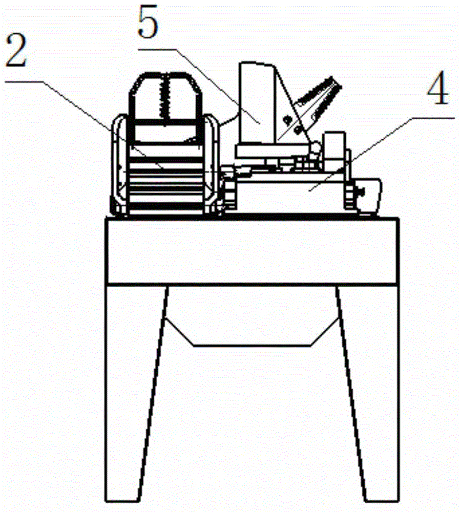
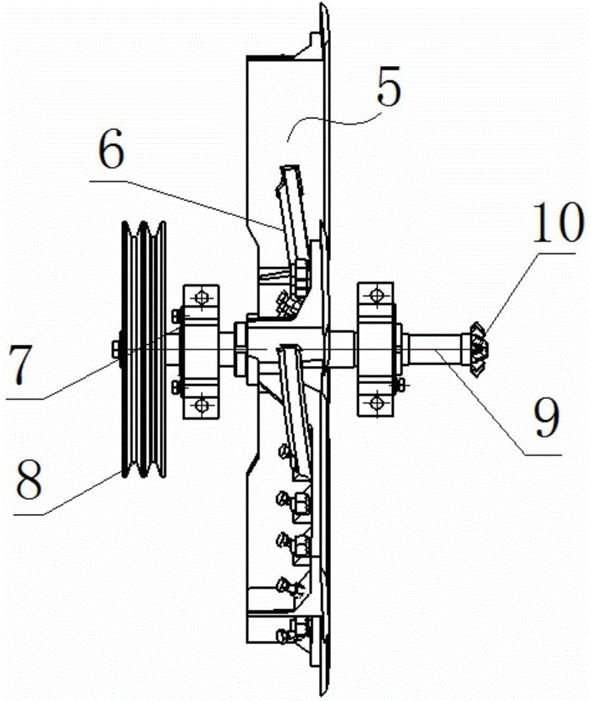
[0052] Such as Figure 1~2 As shown, the present invention includes a base 1, a feeding mechanism 2, an upper cover 3, a speed change mechanism 4 and a main shaft assembly 5, wherein the feeding mechanism 2, the upper cover 3 and the speed change mechanism 4 are all arranged on the base 1, and the main shaft assembly 5 is arranged in the upper cover 3, a power source is provided on one side of the base 1, and the power source drives the main shaft assembly 5 to rotate through a belt transmission mechanism, and the power source is a motor or a motor that can provide rotational power components such as image 3 As shown, the main shaft assembly 5 includes a cutter head assembly 6 for processing crops. The cutter head assembly 6 has a three-layer structure, including a cutter head 12, a cutting knife layer and a crushing knife layer, wherein the cutting knife l...


PUM


Abstract

The invention relates to an agricultural machine, and specifically relates to a hay cutting crusher in which a cut-off tool and a crushing knife are used to operate in a combined manner. The hay cutting crusher comprises a base, a feeding mechanism, an upper cover, a speed change mechanism, and a main shaft assembly. The base is provided with a power source driving the main shaft assembly to rotate. The main shaft assembly is provided with a cutter assembly with a fan blade plate. The main shaft assembly is connected with the feeding mechanism through the speed change mechanism. The cutter assembly comprises a cutter, a cut-off tool layer, and a crushing knife layer. The cut-off tool layer formed by a plurality of cut-off tools is arranged on one side of the cutter, close to the feeding mechanism. The crushing knife layer formed by a plurality of crushing knifes is arranged on one side of the cutter, far away from the feeding mechanism. The speed change mechanism comprises a cabinet, a gear shifting transmission mechanism, and a handle assembly. The gear shifting transmission mechanism is arranged in the cabinet and adjusts gears through the handle assembly which is arranged on the upper side of the cabinet. The hay cutting crusher greatly improves forage processing fineness and forage processing efficiency, and realizes diversification of forage processing.

Description

technical field [0001] The invention relates to an agricultural machine, in particular to a hay cutter which adopts the combined operation of a cutting knife and a crushing knife. Background technique [0002] With the development of animal husbandry, animal husbandry has higher and higher requirements for forage processing quality. Commonly used forage processing equipment mainly includes hay cutters and pulverizers, of which the hay cutters in the prior art are only It can cut crops such as grass or straw into small pieces, but cannot further crush each small piece, so the fineness of the processed forage is poor, and the livestock are unwilling to eat it. Usually, follow-up processing is required to improve the fineness of the feed. This not only wastes manpower and material resources, but also greatly reduces the feed processing efficiency. In addition, although there is a speed change mechanism in the prior art hay cutter, the speed change mechanism is only used to redu...

Claims


Application Information

Patent Timeline
Patent Type & Authority Applications(China)
IPC IPC(8): A01F29/04A01F29/10A01F29/09A01F29/14
Inventor 范嘉丽
Owner 范嘉丽
Why Eureka
Try Eureka