
Powder recovery post-processor

A post-processing machine and powder technology, which is applied to the separation of dispersed particles, chemical instruments and methods, combined devices, etc., can solve the problems of increased cost of a single machine, limited use of post-processing machines, and no expansion functions.

Inactive Publication Date: 2016-10-19
MICROJET TECH
View PDF5 Cites 0 Cited by
  • Summary
  • Abstract
  • Description
  • Claims
  • Application Information

AI Technical Summary

Problems solved by technology

However, spraying the surface of the three-dimensional molding with a strong airflow will mix the glued powder and the recyclable powder together, resulting in the collection of the remaining powder that cannot be recycled and reused
Furthermore, the conventional post-processing machine is only used to clean the surface of three-dimensional molded objects without other corresponding expansion functions, such as cleaning and vacuuming the operating machine of the rapid prototyping device, or performing subsequent powder filtration Recycling, etc., so the use of this post-processing machine is really limited, so the cost of a single machine is relatively increased

Method used


Image

  • Powder recovery post-processor
  • Powder recovery post-processor

Examples


Embodiment Construction

[0047] Some typical embodiments embodying the features and advantages of the present invention will be described in detail in the description in the following paragraphs. It should be understood that the present invention can have various changes in different aspects without departing from the scope of the present invention, and the descriptions and illustrations therein are used as illustrations in nature rather than limiting the present invention .

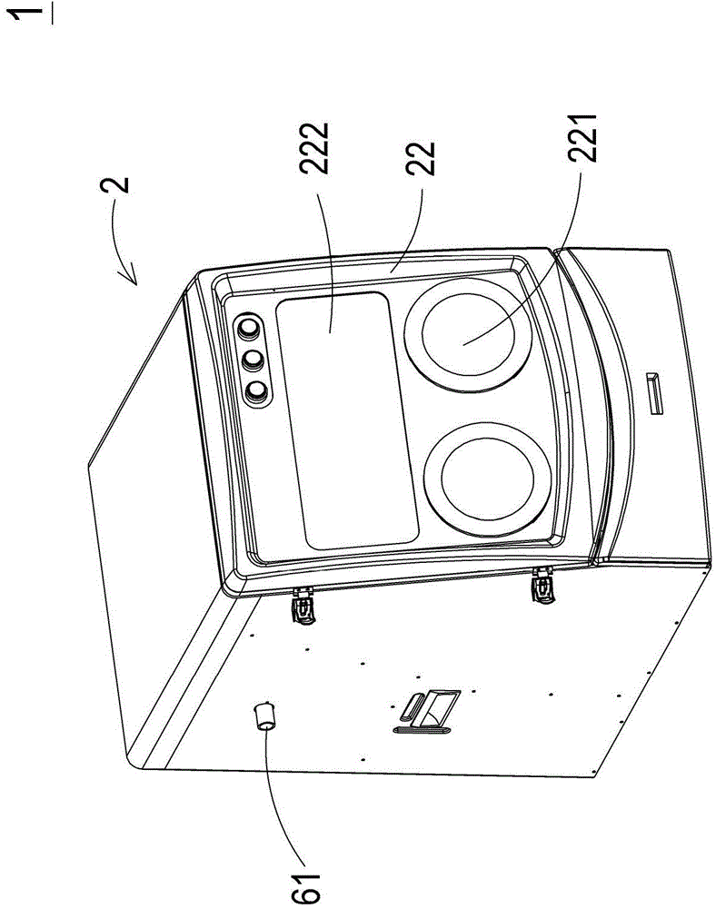
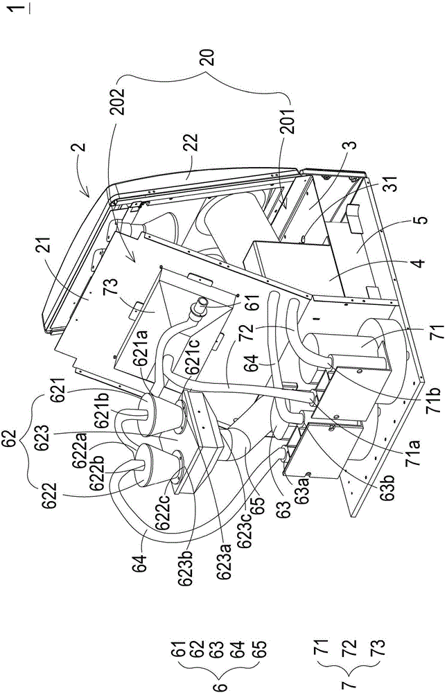
[0048] Please also see figure 1 and figure 2 , which are respectively the structural schematic diagram of the powder recovery post-processing machine of the preferred embodiment of the present invention and figure 1 A schematic diagram of the internal structure of the powder recovery post-processing machine shown. As shown in the figure, the powder recovery post-processing machine 1 of the present invention is suitable for a three-dimensional molding device (not shown), and is used to move the three-dimensional molding (not ...


PUM


Abstract

The present invention relates to a powder recovery post-processor, which comprises a shell, a powder collecting device, a dust collecting system and a dust removal system. The dust collecting system consists of a dust collecting joint, a cyclone dust collecting device, a first air draught device and a plurality of transmission tubes. The plurality of transmission pipes are sequentially connected to the dust collecting joint, the cyclone dust collecting device, the first air draught device and the powder collecting device. The dust collecting joint is arranged in an external dust collecting tube, so as to collect dust into the dust collecting system and then introduce the dust to feeding powder collecting device. The dust removal system comprises a second air draught device and a plurality of guide tubes, wherein the plurality of guide tubes are communicated with a first space, and sequentially connected to the second air draught device and the powder collecting device, so that the remaining powder suspended in the first space enters the dust removal system, and then the powder is sent to the powder collecting device.

Description

【Technical field】 [0001] The invention relates to a powder recovery post-processing machine, especially a powder recovery post-processing machine suitable for a three-dimensional forming device. 【Background technique】 [0002] Rapid Prototyping (RP technology for short) is a technology derived from the concept of building a pyramid layer by layer, which can quickly and cost-effectively shape the designer's idea in a short time and present it to the public. Its main feature is the quickness of forming, which can automatically and quickly convert any complex shape design into a 3D solid model without any tools, molds and jigs, which greatly shortens the development cycle of new products And reduce the cost of research and development, and can ensure the time to market of new products and the success rate of new product development. It promotes a more complete relationship among technical personnel, as well as between technical personnel and non-technical personnel such as ente...

Claims


Application Information

Patent Timeline
IPC IPC(8): B01D50/00
Inventor 奚国元陈智凯黄启峰
Owner MICROJET TECH
Learn More