egr check valve and internal combustion engine and automobile using the valve
An internal combustion engine and check valve technology, applied in mechanical equipment, engine components, engine control, etc., can solve the problems of inability to adapt to the working load of the internal combustion engine, failure of sealing coordination, easy damage, etc., to achieve fast response speed, stable and reliable flow rate. Sexual effect
- Summary
- Abstract
- Description
- Claims
- Application Information
AI Technical Summary
Problems solved by technology
Method used
Image
Examples
Embodiment 1
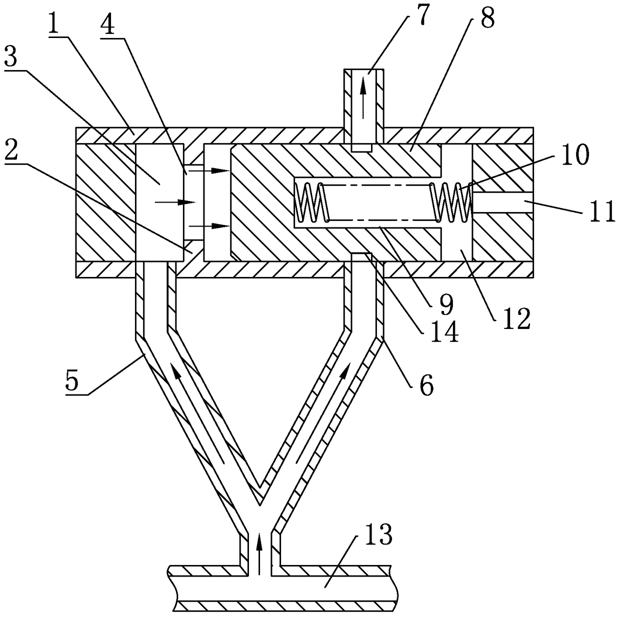
[0036] like figure 1 As shown, the EGR check valve includes a housing 1, a partition 2, a left cavity 3, a through hole 4, a left guide branch 5, a right guide branch 6, an intake branch 7, a valve core 8, a slot 9, a spring 10, Air vent 11, right cavity 12, exhaust pipe 13, ring groove 14.
[0037] The closed cylindrical thin-walled shell 1 is provided with a partition 2, the partition 2 divides the inner cavity of the shell 1 into a left cavity 3 and a right cavity 12, and the partition 2 is provided with a connection between the left cavity 3 and the right cavity. The through hole 4 of 12, the spool 8 is slidably fitted in the right cavity 12, the spool 8 and the inner circumferential wall of the right cavity 12 are sealed and fitted, the spool 8 is provided with a slot 9 opening to the right, the middle part of the spool 8 is in contact with the An annular groove 14 is provided on the adjacent outer wall of the right chamber 12. As a preference, the annular groove 14 is c...
Embodiment 2
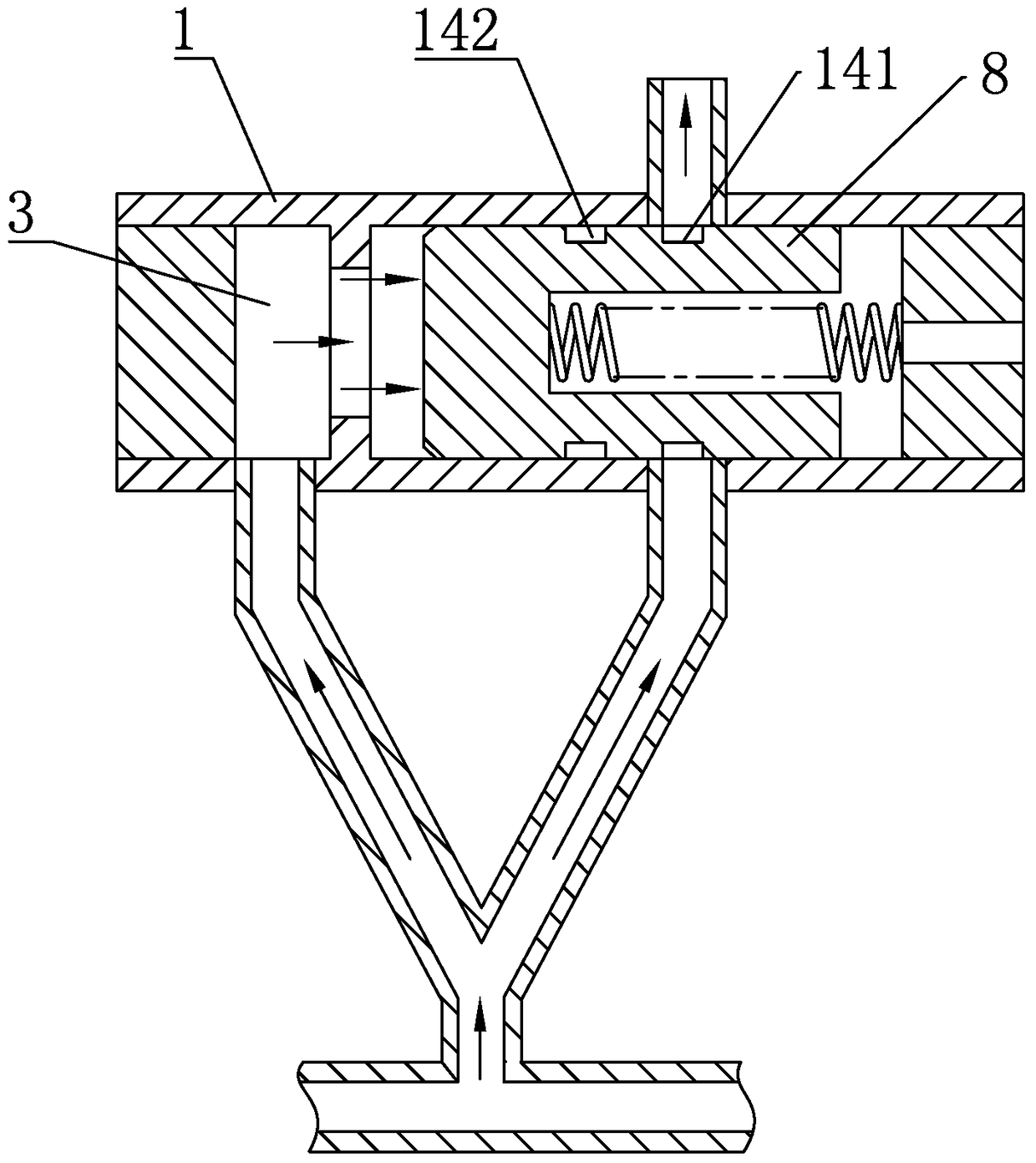
[0047] like figure 2 As shown, the difference of this embodiment with respect to Embodiment 1 is that two annular grooves are provided on the outer wall of the valve core 8, namely the first annular groove 141 and the second annular groove 142, and a plurality of annular grooves are set and adjacent The spacing of the ring groove can change the exhaust gas recirculation amount of the internal combustion engine under different load conditions, and use the EGR system to reduce the nitrogen oxides in the exhaust gas.
Embodiment 3
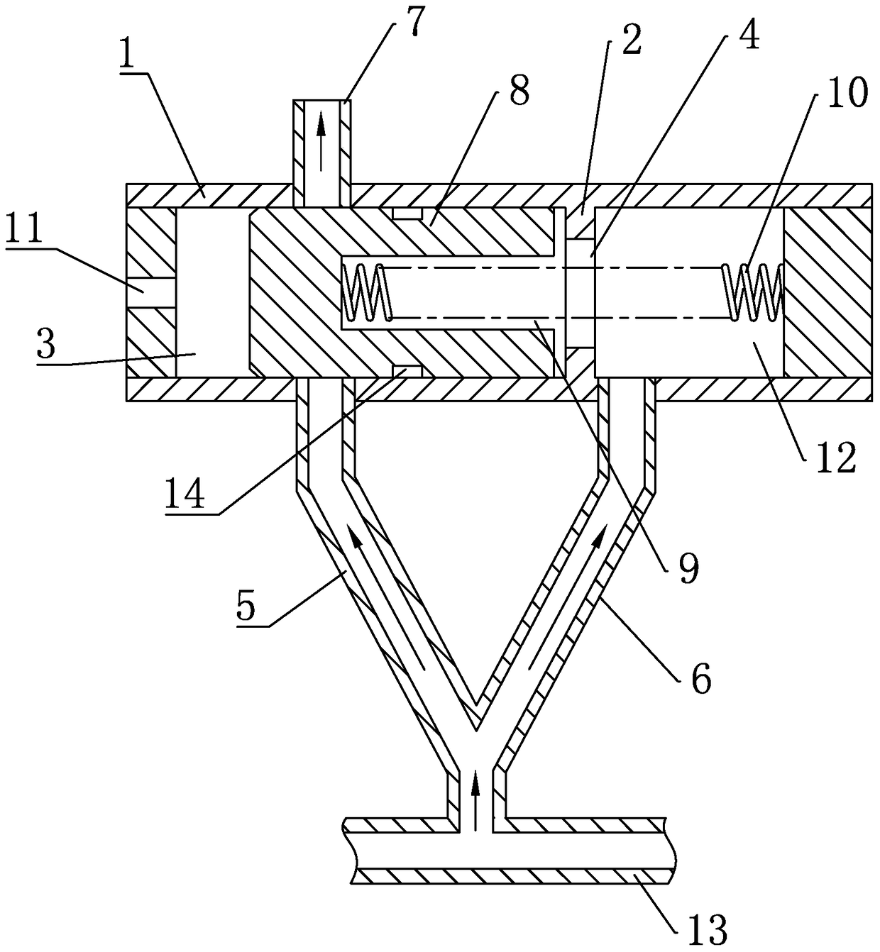
[0049] The difference between this embodiment and embodiment 1 is: as image 3 As shown, the valve core 8 is slidingly fitted in the left chamber 3, the intake branch pipe 7 is connected to the outer wall of the left chamber 3 and the centerlines of the left guide branch pipe 5 and the intake branch pipe 7 are located in the same housing cross section, and the spring 10 Penetrated in the through hole 4, one end of the spring 10 is fixedly connected to the left inner wall of the slot 9, the other end of the spring 10 is fixedly connected to the right inner wall of the housing 1, and the vent hole 11 is provided on the left side of the left cavity 3 On the wall, the spring 10 is always in tension during the sliding process of the spool 8. Spool 8 matches the length of left chamber 3, so that when spool 8 slides between the left and right limit positions of left chamber 3, left chamber 3 is not communicated with intake branch pipe 7 and left guide branch pipe 5.
[0050] The wor...
PUM
 Abstract
Description
Claims
Application Information
 - R&D
- Intellectual Property
- Life Sciences
- Materials
- Tech Scout
- Unparalleled Data Quality
- Higher Quality Content
- 60% Fewer Hallucinations
Browse by: Latest US Patents, China's latest patents, Technical Efficacy Thesaurus, Application Domain, Technology Topic, Popular Technical Reports.
© 2025 PatSnap. All rights reserved.Legal|Privacy policy|Modern Slavery Act Transparency Statement|Sitemap|About US| Contact US: help@patsnap.com


