Disaster recovery switching method and device based on virtual machine

A technology of disaster recovery switch and virtual machine, applied in the field of virtual machine-based disaster recovery switch method and device, can solve problems such as waste of resources, poor disaster recovery capability, user impact, etc., to reduce resource waste, improve disaster recovery capability and The effect of service reliability

Active Publication Date: 2016-10-19
TENCENT TECH (SHENZHEN) CO LTD +1
View PDF5 Cites 6 Cited by
  • Summary
  • Abstract
  • Description
  • Claims
  • Application Information

AI Technical Summary

Problems solved by technology

[0003] During the research and practice of the prior art, the inventors of the present invention found that, in this solution, if any part of the business channel between eth1 and the gateway of the external network fails, such as the switch is powered off or the hardware is damaged, the business The channel will be interrupted, and the virtual machine will not be able to continue to provide external services. It can only wait for the staff to repair it, which will have a great impact on users, poor disaster recovery capabilities, and low service reliability.
If a new backup service channel is added, a large amount of investment is required and the existing network needs to be transformed, and the newly added service channel will be idle most of the time, resulting in a great waste of resources

Method used


Image

  • Disaster recovery switching method and device based on virtual machine
  • Disaster recovery switching method and device based on virtual machine
  • Disaster recovery switching method and device based on virtual machine

Examples


no. 1 example

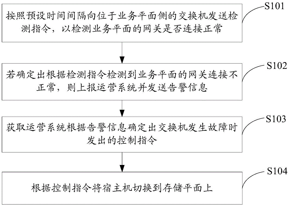
[0029] see figure 1 , figure 1 It is a schematic flowchart of the virtual machine-based disaster recovery switching method provided by the first embodiment of the present invention. The methods include:

[0030] In step S101, a detection instruction is sent to the switch on the service plane side according to a preset time interval, so as to detect whether the gateway of the service plane is connected normally.

[0031] In step S102, if it is determined that the gateway connection of the service plane is abnormal according to the detection instruction, report to the operation system and send an alarm message.

[0032] Wherein, the steps S101 and S102 may specifically be:

[0033] It can be understood that the virtual machine-based disaster recovery switching method can be run on a server based on a monitor, and the monitor continues to detect the connection status of the service plane gateway, and if the connection is abnormal, it will report The operation system sends an ...

no. 2 example

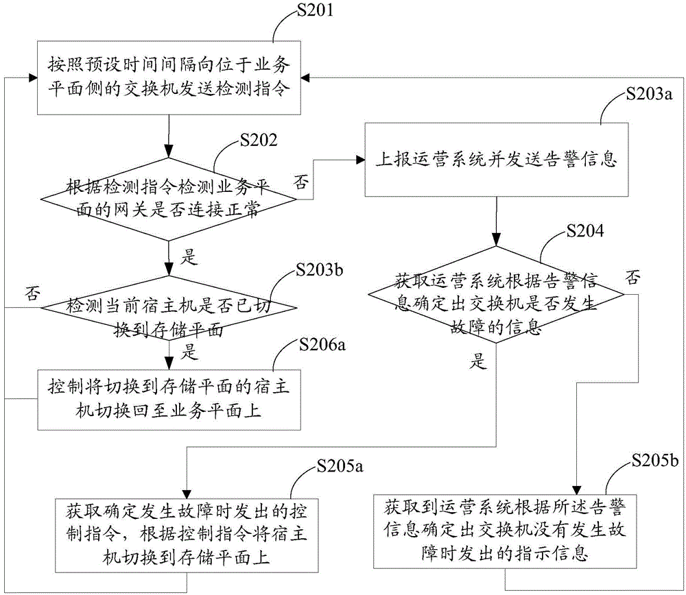
[0044]Please refer to FIG. 2 . FIG. 2 is a schematic flowchart of a virtual machine-based disaster recovery switching method according to a second embodiment of the present invention. Wherein, the virtual machine-based disaster recovery switching method runs on a server based on a monitor, and the monitor continues to detect the connection status of the service plane gateway. If the connection is not normal, it will report to the operation system and give an alarm. Receive an alarm to confirm the status of the switch, and if it is determined that the switch is faulty, control the switching of all hosts to the storage plane.

[0045] Different from the first embodiment, this embodiment mainly describes the disaster recovery switching method in detail for the virtual machine disaster recovery switching system. The methods include:

[0046] In step S201, a detection instruction is sent to the switch located on the service plane side according to a preset time interval.

[0047]...

no. 3 example

[0068] Please refer to FIG. 3 . FIG. 3 is a schematic flowchart of a virtual machine-based disaster recovery switching method according to a third embodiment of the present invention. Same as the above embodiment, the virtual machine-based disaster recovery switching method runs on the server based on the monitor, and the monitor continues to detect the connection status of the service plane gateway. If the connection is abnormal, it will report to the operating system and give an alarm. The operation system receives an alarm to confirm the status of the switch. If it is determined that the switch is faulty, it controls to switch all hosts to the storage plane. .

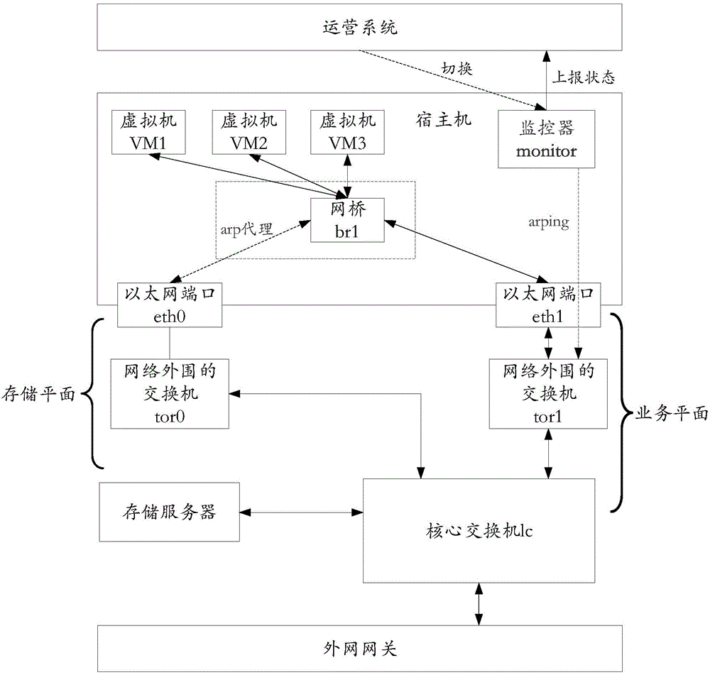
[0069] Different from the second embodiment, this embodiment is mainly based on the above-mentioned Figure 2b The shown disaster recovery switching system describes in detail the process of switching between the storage plane and the service plane.

[0070] Can refer to Figure 3a , which is a schematic diagram ...


PUM


Abstract

The invention discloses a disaster recovery switching method and device based on a virtual machine. The disaster recovery switching method comprises steps of transmitting a detection order to a switch positioned on a service plane side according to a preset time interval in order to detect whether connection of a gateway of the service plane is normal or not, if the gateway connection of the service plane is detected to be not normal according to the detection order, reporting to an operation system and sending alarming information, obtaining a control order transmitted by the operation system when the operation system determines the switch has faults according to the alarming information, and switching a host machine to a memory plane according to the control order. The embodiment of the disaster recovery switching method and device can transfer a flow of the service plane to the memory plane on the basis of that the current hardware facility is not changed, multiplex a current storage channel to bear service transmission during a fault period, reduce resource waste, guarantee that the service that the virtual machine on the host machine provides to the external is not interrupted and dramatically improve reliability of the disaster recovery capability and service of the virtual machine during the external service of the virtual machine.

Description

technical field [0001] The invention belongs to the technical field of communications, and in particular relates to a virtual machine-based disaster recovery switching method and device. Background technique [0002] A virtual machine (VM, Virtual Machine) refers to a complete computer system that is simulated by software and has complete hardware system functions and runs in a completely isolated environment. In the existing solution, the virtual machine can provide external services through the service channel, where the service channel is: virtual machine -> br1 (Bridge, bridge) -> eth1 (Ethernet, Ethernet port) -> tor1 (located in the network peripheral switch)->lc (core switch)->external network gateway; it can also provide customers with distributed storage services through the storage channel, where the storage channel is: virtual machine disk->host machine block device->eth0->tor0- >lc->storage server. [0003] During the research and ...

Claims


Application Information

Patent Timeline
Patent Type & Authority Applications(China)
IPC IPC(8): H04L12/24H04L1/22
Inventor 陈康刘颖曹德华
Owner TENCENT TECH (SHENZHEN) CO LTD
Why Eureka
Try Eureka