A split-flow multi-air duct dust collection device

A dust collection device and multi-air duct technology, which is applied in the field of split-flow multi-air duct dust collection devices, can solve problems such as lack, and achieve the effects of low noise, strong dust absorption ability, and good filtering effect

Active Publication Date: 2020-12-29
NINGBO HAIJI ELECTRIC APPLIANCE
View PDF7 Cites 0 Cited by
  • Summary
  • Abstract
  • Description
  • Claims
  • Application Information

AI Technical Summary

Problems solved by technology

However, the current vacuum cleaners are still lacking in the setting of the air duct, the separation ability and efficiency of dust and air, etc.

Method used


Image

  • A split-flow multi-air duct dust collection device
  • A split-flow multi-air duct dust collection device
  • A split-flow multi-air duct dust collection device

Examples


Embodiment 1

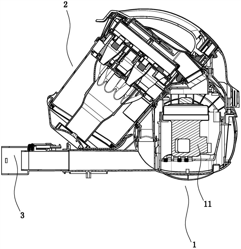
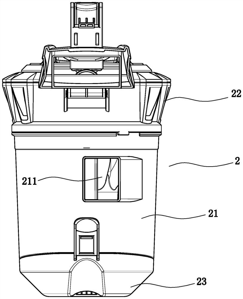
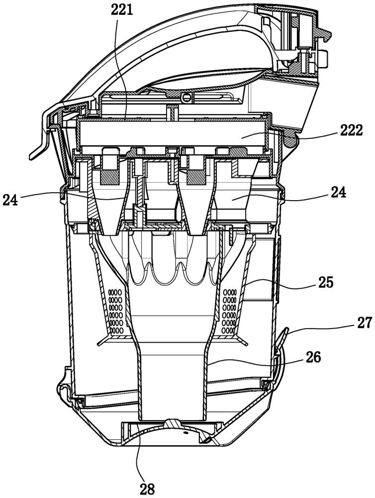
[0026] Embodiment 1: as Figure 1 to Figure 4 In the shown embodiment, a split-type multi-air duct dust collection device includes a main body 1 and a suction motor 11. The dust cup body includes a cup body 21, a cup cover 22 cooperating with the cup body, and a cup bottom 23 cooperating with the cup body. The cup body is provided with a cup body air inlet connected to the suction seat, and a number of shunts are arranged in the dust cup body. Cyclone cone 24, the diversion cyclone cone is provided with a tangential air inlet branch pipe 242 communicating with the interior of the diversion cyclone cone, the upper and lower ends of the diversion cyclone cone are open and the upper opening is larger than the lower opening, the upper end of each diversion cyclone cone The openings are all communicated with the air inlet end of the suction motor through the middle air duct, and the air outlet end of the suction motor is communicated with the outer air outlet on the main body. The...

Embodiment 2

[0029] Embodiment 2: the basic structure and implementation mode of this embodiment are the same as embodiment 1, and its difference is, as Figure 5 to Figure 9As shown in , the bottom of the battery case 4 is provided with a main vent that communicates with the outside world, and the top of the battery case is provided with several auxiliary vents that communicate with the outside world. The battery case is provided with a shock-absorbing frame 412, and the battery pack and The shock-absorbing frame is connected, a number of shock-absorbing springs 4211 are arranged between the shock-absorbing frame and the bottom of the battery case, a number of vertically arranged guide posts 421 are provided at the lower end of the shock-absorbing frame, and a A plurality of guide sleeves 422, the guide posts correspond to the guide sleeves one by one and the guide posts and the corresponding guide sleeves are slidably matched, the shock absorbing springs correspond to the guide posts one ...


PUM


Abstract

The invention discloses a flow-splitting multi-air-channel dust collecting device. The flow-splitting multi-air-channel dust collecting device comprises a main machine body, an air sucking motor, a dust cup and a suction hole base, wherein the dust cup comprises a cup body, a cup cover and a cup bottom, the cup body is provided with a cup air inlet, the interior of the dust cup is provided with a plurality of flow-splitting cyclone conical barrels, tangential air inlet branch pipes are arranged on the flow-splitting cyclone conical barrels, the upper end and the lower end of each barrel are open, the opening in the upper end is larger than the opening in the lower end, the openings in the upper ends of the flow-splitting cyclone conical barrels communicate with the air inlet end of the air sucking motor through middle air channels, the air outlet end of the air sucking motor communicates with an external air exhaust hole in the main machine body, filtering racks are arranged in cover air channels, and air inlet sponge is arranged on the filtering racks. The flow-splitting multi-air-channel dust collecting device has the beneficial effects that the air channels are reasonable in structure, and the separation and collection of dust can be effectively completed; the dust collecting capacity is strong, the filtering effect is good, and the air exhaust cleanliness can be guaranteed; an electricity storage structure is available, therefore, the progressive flow-splitting dust collecting device can work without an electric wire, and in addition, the structures are strong in cooling and heat dissipating capacities and shock resistance; the integral stability is good, and the noise is small.

Description

technical field [0001] The invention belongs to the technical field of vacuum cleaners, in particular to a split-flow multi-air duct dust collection device. Background technique [0002] With the development of the times and the improvement of living standards, vacuum cleaners, especially household vacuum cleaners, have been widely used. A vacuum cleaner is an electrical appliance that uses a motor (suction motor) to generate negative air pressure in a sealed housing to suck in dust or garbage. The main function of the current vacuum cleaner is to recycle and clean up the dust and garbage on the floor, carpet, etc. in the home. However, the current vacuum cleaners are still lacking in the setting of the air duct, the separation ability and efficiency of dust and air, and the like. Contents of the invention [0003] In order to overcome the deficiencies in the prior art, the present invention provides a filter with reasonable structure, which can effectively complete func...

Claims


Application Information

Patent Timeline
Patent Type & Authority Patents(China)
IPC IPC(8): A47L9/16
CPCA47L9/1608A47L9/1616A47L9/1691
Inventor 周荣郑良宝
Owner NINGBO HAIJI ELECTRIC APPLIANCE
Why Eureka
Try Eureka