Connecting structure of middle phalanx and proximal phalanx of prosthetic finger

A technology of connecting structure and proximal knuckles, applied in the field of bionic hands, can solve the problems of bending residual deformation of extension springs, prone to failure, not distinguishing between the distal knuckles of fingers and the proximal knuckles of fingers, etc., so as to eliminate the effect of bending moment. , the effect of improving the performance

Active Publication Date: 2016-10-26
ZORPIA ROBOT CO LTD
View PDF4 Cites 3 Cited by
  • Summary
  • Abstract
  • Description
  • Claims
  • Application Information

AI Technical Summary

Problems solved by technology

[0007] 1. The base knuckles of the prosthetic fingers have many components, and the assembly relationship is complicated. It is difficult to effectively and accurately locate the components, and the assembly is difficult. In particular, the base knuckle structures of some existing prosthetic fingers have simple assembly structures As a result, the working reliability of the base knuckle is poor, and it is prone to failure
[0008] 2. In some existing prosthetic fingers, the connection structure between the base phalanx and the base joint of the prosthesis finger is complicated, and the base phalanx of the finger is difficult to assemble on the base joint structure, and cannot be assembled simply and effectively
[0009] 3. For some existing prosthetic fingers that use cable transmission for proximal knuckles, the proximal end of the transmission rope is connected to the worm gear, but the specific connection structure adopted is not convenient for assembly, and the proximal end of the transmission rope is also prone to fall off. Not conducive to reliable use of prosthetic hands
[0010] 4. For some existing prosthetic fingers, the proximal knuckles are driven by cables. Frequent finger flexion and finger extension operations will easily cause the transmission rope to be rubbed and scratched on the base knuckles of the finger. Long-term use will easily cause the transmission rope to wear or even break , affecting the service life of the cable transmission mechanism
[0011] 5. In some existing prosthetic fingers, the proximal knuckle of the finger and the base knuckle of the finger are connected by a stretch spring to realize the automatic reset of the proximal knuckle of the finger when the finger is extended, and the end of the stretch spring is fixed. The connection method, so the tension spring is frequently subjected to the compound action of tension and bending moment, and long-term use will cause the tension spring to undergo bending residual deformation
This will cause the fingers of the prosthesis to flex and spread out of position, reducing the performance of the prosthetic fingers and prosthetic hands
[0012] 6. Some existing prosthetic fingers do not distinguish between the far knuckle and the near knuckle of the finger in structure, which is not convenient for the assembly of the near knuckle of the finger and other parts, or the near knuckle of the finger and the far knuckle of the finger The connection method of using end face bonding and then connecting with other connectors has poor connection reliability and the structure is not beautiful enough.
[0013] 7. The existing prosthetic fingers, due to the aforementioned problems in some of their structures, lead to poor working reliability of the entire prosthetic finger and are not easy to assemble
However, in some existing prosthetic thumbs, the structure between the proximal knuckle of the thumb and the base knuckle of the thumb is very different from the connection structure between the proximal knuckle and the distal knuckle of the general prosthetic finger (non-thumb), This requires the special design and manufacture of the structure of the thumb, or the special design and manufacture of the structure of the proximal knuckle of the thumb and the base knuckle of the thumb. The difference between the prosthetic thumb and the general prosthetic finger will cause additional workload and processing costs. The versatility of components is also poor, which is not conducive to reducing costs
[0015] 9. The thumb has two postures: opposite palm and side palm. Therefore, the thumb of the prosthetic limb needs to perform posture rotation movement, but the installation structure adopted by the thumb of the existing prosthetic limb, the wires connected to the motor are drawn from the side, so that the thumb of the prosthetic limb is in the working position. When changing the posture of the side palm and the opposite palm, the wires are pulled, and long-term use will cause the wires to break. In fact, the wires of this type of prosthetic thumb are often broken.
[0016] 10. Due to the above-mentioned problems in the existing prosthetic thumb, the entire prosthetic finger has a high cost, is prone to failure, and has poor working reliability;
[0017] 11. For some existing prosthetic hands, the general prosthetic fingers (four other prosthetic fingers except the thumb) are installed in the following way: the general prosthetic finger and the finger connector of the prosthetic hand are connected by a finger axial single screw, Generally, when the finger is straightened, the single screw in the axial direction of the finger is in the same direction as the finger, and the connection is not reliable. Short-term use will cause the connection to loosen.
[0018] 12. The existing prosthetic hands, due to the above-mentioned problems in some of their structures, lead to poor reliability and high cost of prosthetic hands

Method used


Image

  • Connecting structure of middle phalanx and proximal phalanx of prosthetic finger
  • Connecting structure of middle phalanx and proximal phalanx of prosthetic finger
  • Connecting structure of middle phalanx and proximal phalanx of prosthetic finger

Examples


Embodiment Construction

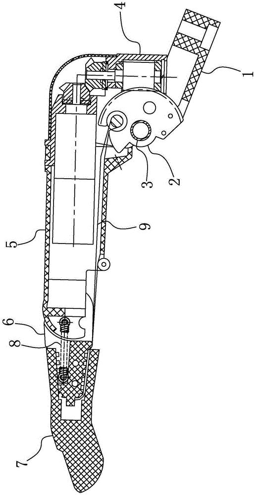
[0037] The structure of the prosthetic hand, the prosthetic finger and the parts thereof according to the embodiment of the present invention will be described in detail below with reference to the accompanying drawings.

[0038] In order to facilitate an accurate understanding of the description of this embodiment, before proceeding to the description, explain the orientation words mentioned in this embodiment: on the prosthetic finger and specific components, "distal end" refers to the end close to the fingertip, "Proximal end" is opposite to "far end", "proximal end" refers to the end close to the root of the finger (or the base of the finger joint or the palm); "upper", which represents the orientation, refers to the position between the top of the finger and the back of the hand when the finger is straightened. The orientation corresponding to the orientation; the "down" representing the orientation refers to the orientation corresponding to the orientation of the finger a...


PUM


Abstract

The invention provides a connecting structure of a middle phalanx and a proximal phalanx of a prosthetic finger. The connecting structure comprises a finger proximal phalanx (5), a finger middle phalanx (6) and a tension spring (8), wherein the finger middle phalanx (6) is rotatablely connected onto the finger proximal phalanx (5); a stretching spring far end cylindrical pin (81) is fixed on the finger middle phalanx (6); a tension spring near end cylindrical pin (82) is fixed on the proximal phalanx (5); the axial lines of the tension spring far end cylindrical pin (81) and the tension spring near end cylindrical pin (82) are parallel to the rotating axial line of the finger middle phalanx (6); and the two ends of the tension spring (8) sleeve the tension spring far end cylindrical pin (81) and the tension spring near end cylindrical pin (82). In a process that the finger middle phalanx rotates around the finger proximal phalanx, the far end of the tension spring can rotate around the tension spring far end cylindrical pin; and the bending moment effect received by the tension spring can be greatly reduced or even eliminated.

Description

technical field [0001] The invention relates to a bionic hand, in particular to a prosthetic hand for disabled people, its fingers and part of the structure. Background technique [0002] Human hands generally have five fingers, followed by thumb, index finger, middle finger, ring finger and little finger. Except that the thumb has a special movement law, the movement laws of the other four fingers are basically the same. Each finger is divided into three knuckles, which are the base knuckle, the proximal knuckle and the distal knuckle in turn. They are connected by joints in corresponding positions, and the nails grow on the far knuckles. For some disabled people, it is necessary to utilize the prosthetic hand to realize the basic functions of the human hand. [0003] Before 2007, the most sold prosthetic hand on the market was the single-free prosthetic hand produced by OTTOBOCK in Germany. This type of prosthetic hand only has basic opening and closing functions. Moveme...

Claims


Application Information

Patent Timeline
IPC IPC(8): A61F2/54
Inventor 白劲实
Owner ZORPIA ROBOT CO LTD
Why Eureka
Try Eureka