Rolling mill

A rolling mill and roll technology, applied in the field of rolling mills, can solve problems such as poor stability, poor rolling precision, and low operating efficiency, and achieve the effects of improving strength and rigidity, convenient and quick operation, and improving operating efficiency

Active Publication Date: 2016-10-26
BEIJING JINGCHENG RUIXINCHANGCAI ENG TECH
View PDF6 Cites 6 Cited by
  • Summary
  • Abstract
  • Description
  • Claims
  • Application Information

AI Technical Summary

Problems solved by technology

[0002] The closed rolling mill of the prior art has heavy weight, long stress loop, large bounce, poor rigidity of the rolling mill, and poor rolling precision
The roll gap of the rolling mill can only be adjusted on one side. The pressing device can only press down the upper roll, and the lower roll can only be adjusted by shims. The adjustment of the roll gap is very inconvenient
Moreover, it takes a long time to replace the roller system online, the operation and maintenance are inconvenient, and the operation efficiency is very low
There is also a short stress line rolling mill in the prior art, which has a short stress loop and relatively high rigidity; but the short stress line rolling mill is still insufficient in strength and poor in stability, and is difficult to adapt to the rolling of alloy steel and special steel

Method used


Image

  • Rolling mill
  • Rolling mill
  • Rolling mill

Examples


Embodiment Construction

[0053] The above and other technical features and advantages of the present invention will be clearly and completely described below in conjunction with the accompanying drawings. Apparently, the described embodiments are only some of the embodiments of the present invention, not all of them.

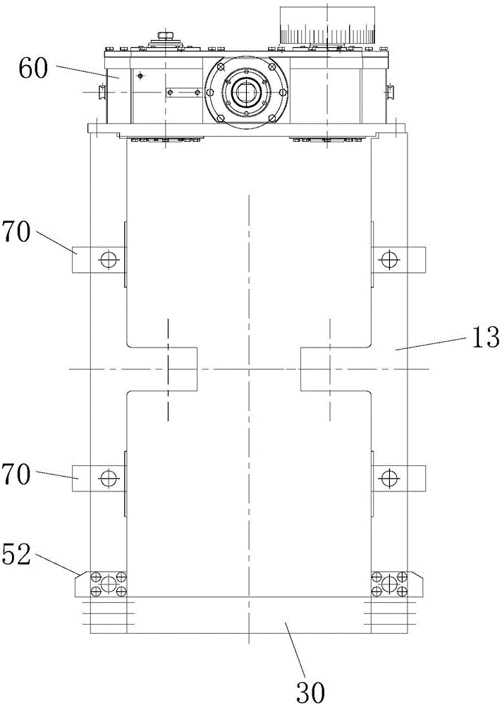
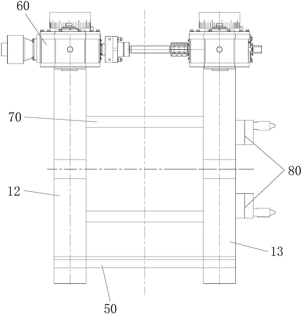
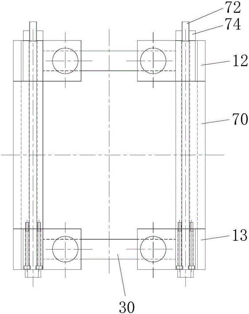
[0054] see figure 1 , figure 2 and image 3 As shown, a rolling mill includes a stand, a roll mechanism 20 and a pressing mechanism. The frame includes a left archway 12 and a right archway 13 arranged in parallel, and at least a pair of guide beams 70 horizontally connected between the left archway 12 and the right archway 13 . see Figure 4 , Figure 5 and Figure 6 As shown, the left archway 12 and the right archway 13 all include two opposite and vertically arranged columns 14 and a horizontally arranged connecting beam 30, and the two ends of the connecting beam 30 are detachably connected to the bottoms of the two columns 14 respectively; The guide crossbeams 70 are symmetr...


PUM

PropertyMeasurementUnit
thicknessaaaaaaaaaa

Abstract

The invention provides a rolling mill. The rolling mill comprises a rack, roller mechanisms and pressing mechanisms. The rack comprises a left archway, a right archway and at least one pair of guide cross beams, wherein the guide cross beams are horizontally connected between the left archway and the right archway. The left archway and the right archway each comprise two stand columns and a connecting cross beam, wherein the two stand columns are arranged oppositely and vertically, and the two ends of the connecting cross beam are detachably connected to the bottoms of the two stand columns correspondingly. The guide cross beams in each pair are arranged between the left archway and the right archway in a front-back symmetry mode, and the two ends of each guide cross beam are detachably connected with the corresponding stand column of the left archway and the corresponding stand column of the right archway correspondingly. Both an upper roller assembly and a lower roller assembly slidably abut against the stand columns. The pressing mechanisms drive the upper roller assembly and the lower roller assembly to slide on the stand columns in a face-to-face mode or oppositely correspondingly, and roller seams are symmetrically decreased or increased through the sliding. According to the rolling mill, a roller system can be disassembled and assembled rapidly, and real-time online symmetrical adjustment of the roller seams is achieved; and since a prestressing mechanism is arranged, on-load pressing can be achieved.

Description

technical field [0001] The invention relates to the technical field of steel rolling machinery, in particular to a rolling mill. Background technique [0002] The closed rolling mill in the prior art has heavy weight, long stress loop, large bounce, poor rolling mill rigidity and poor rolling precision. The roll gap of the rolling mill can only be adjusted on one side, the pressing device can only press down the upper roll, and the lower roll can only be adjusted by shims, so the adjustment of the roll gap is very inconvenient. Moreover, it takes a long time to change the roller system online, the operation and maintenance are inconvenient, and the operation efficiency is very low. There is also a short stress line rolling mill in the prior art, which has a short stress loop and relatively high rigidity; however, the short stress line rolling mill is still insufficient in strength and poor in stability, and is difficult to adapt to the rolling of alloy steel and special ste...

Claims


Application Information

Patent Timeline
Patent Type & Authority Applications(China)
IPC IPC(8): B21B13/02B21B31/04B21B31/24
CPCB21B13/023B21B31/04B21B31/24B21B2013/021
Inventor 赵英彪刘炜何巍巍范思石王任全孙长城
Owner BEIJING JINGCHENG RUIXINCHANGCAI ENG TECH
Why Eureka
Try Eureka