Pipe expander

A tube expander and expander technology, which is applied in the field of tube expanders, can solve the problems of complex structure, inconvenient to carry, and heavy weight, and achieve the effects of reasonable structural design, convenient manual operation, and convenient use

Inactive Publication Date: 2016-10-26
ZHEJIANG XINCHANG SANRUI HORNSEY STAMPING IND
View PDF0 Cites 0 Cited by
  • Summary
  • Abstract
  • Description
  • Claims
  • Application Information

AI Technical Summary

Problems solved by technology

[0002] At present, the tube expanders used in the market are generally hydraulically driven and hinged. The advantage is that the expansion distance in the radial direction is large. The disadvantage is that the tube expander is large in size, heavy in weight, complex in structure, and high in production costs. And it is inconvenient to carry, which is not conducive to on-site installation or repair use
In order to solve the above problems, a tube expander has appeared, its structure includes a driving cylinder, a front cover at one end of the tube expander, a rear cover at the other end of the tube expander, an expander inside the tube expander and an expander outside the tube expander. The driving cylinder is installed outside the front cover of the tube expander. The expansion head is a small cone. The piston rod of the driving cylinder is connected with the small cone through the front cover. The expansion body is a split valve connected with the front cover and the rear cover. The cone, the split cone and the small cone are matched. Although this kind of tube expander has a simple structure and can generate a large tube expansion force with a small oil pressure, the structure is not compact enough and needs to occupy a large space. If Insufficient operating space during use, the tube expander cannot be used
In addition, because the oil return part of the existing tube expander is generally columnar, when it cooperates with the oil discharge hole, the oil cannot be smoothly returned to the oil storage pipe

Method used


Image

  • Pipe expander
  • Pipe expander

Examples


Embodiment Construction

[0013] The present invention will be further described below in conjunction with the accompanying drawings.

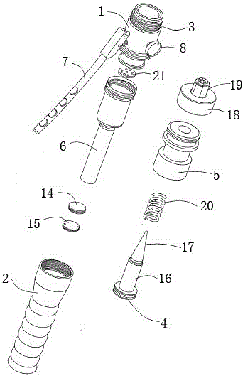
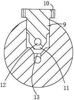
[0014] Such as Figure 1-2 As shown, a tube expander of the present invention includes a piston cylinder 4 comprising a hydraulic pump 1, a handle 2, and a built-in piston 3. The handle 2 and the piston cylinder 4 are respectively arranged at both ends of the hydraulic pump 1, and the opening of the piston cylinder 4 A cylinder head 5 is arranged at the cylinder head 5, and an expansion head is arranged on the cylinder head 5. The handle 2 is connected with the oil pressure pump 1 through the oil storage pipe 6. The outer wall of the oil pressure pump 1 is provided with a hand pressure handle 2, and the oil pressure pump 1 is close to the hand pressure handle 7. An oil return component 8 is arranged on the side; the oil return component 8 includes an oil return rod 9, a rotating handle 10 arranged at one end of the oil return rod 9 and a tapered part 11 arranged at the...


PUM


Abstract

The invention discloses a pipe expander. The pipe expander comprises an oil pressure pump, a handle and a piston cylinder, wherein a cylinder cover is arranged at an opening of the piston cylinder and provided with an expansion head; the handle is connected with the oil pressure pump through an oil storage pipe; a hand pressing handle is arranged on the outer wall of the oil pressure pump, and the oil pressure pump is provided with an oil returning assembly; the oil returning assembly comprises an oil returning rod, a rotary handle and a conical part; the oil pressure pump is internally provided with an oil inlet hole and an oil relief hole; the conical part is matched with the oil relief hole; and a movable block for sealing oil and a sealing block used for sealing the oil storage pipe are arranged in the oil storage pipe. The pipe expander is reasonable in structure design. Through the arranged oil returning rod and rotary handle, and the conical part, the oil inlet hole and the oil relief hole of the other end of the oil retuning rod, it is guaranteed that during use, through matching of the conical part and the oil relief hole, that is, when the conical part is completely inserted into the oil relief hole, the oil in the piston cylinder can not be pressed back into the oil storage pipe, and when the conical part gets away from the oil relief hole, the oil can be conveniently pressed into the oil storage pipe. The pipe expander is convenient to use, simple in structure, light in weight and convenient to operate manually.

Description

technical field [0001] The invention relates to a tube expander. Background technique [0002] At present, the tube expanders used in the market are generally hydraulically driven and hinged. The advantage is that the expansion distance in the radial direction is large. The disadvantage is that the tube expander is large in size, heavy in weight, complex in structure, and high in production costs. And it is inconvenient to carry, and it is not conducive to on-site installation or repair use. In order to solve the above problems, a tube expander has appeared, its structure includes a driving cylinder, a front cover at one end of the tube expander, a rear cover at the other end of the tube expander, an expander inside the tube expander and an expander outside the tube expander. The driving cylinder is installed outside the front cover of the tube expander. The expansion head is a small cone. The piston rod of the driving cylinder is connected with the small cone through the f...

Claims


Application Information

Patent Timeline
Patent Type & Authority Applications(China)
IPC IPC(8): B21D39/08
CPCB21D39/08
Inventor 陈均石丽腾
Owner ZHEJIANG XINCHANG SANRUI HORNSEY STAMPING IND
Why Eureka
Try Eureka