Eureka AIR delivers breakthrough ideas for toughest innovation challenges, trusted by R&D personnel around the world.

Motor vehicle lamp LED light source positioning method based on machine vision

A technology of LED light source and machine vision, which is applied in the direction of metal processing equipment, milling machine equipment, milling machine, etc., can solve the problems of the whole light shape change, the position deviation of LED light source, the influence of the light distribution of the car light, etc., so as to improve the effect and improve the light distribution performance and improve assembly accuracy

Active Publication Date: 2016-10-26
CHANGZHOU XINGYU AUTOMOTIVE LIGHTING SYST
View PDF10 Cites 2 Cited by
  • Summary
  • Abstract
  • Description
  • Claims
  • Application Information

AI Technical Summary

Problems solved by technology

Now when the circuit board is making the printed circuit, the mounting holes have been processed, and then the LED light source is soldered on the circuit board with the mounting holes, which is constrained by the mounting equipment, welding process and assembly process, etc. The position of the LED light source is deviated, and the position of the LED light source in the housing has a fatal impact on the light distribution of the entire car light.
When the position of the LED light source in the housing cannot accurately reach the designed position, the entire light shape after assembly will change, and the light distribution of the car light cannot achieve the best effect, resulting in the LED light source not meeting the light distribution requirements.

Method used


Image

  • Motor vehicle lamp LED light source positioning method based on machine vision
  • Motor vehicle lamp LED light source positioning method based on machine vision
  • Motor vehicle lamp LED light source positioning method based on machine vision

Examples


Embodiment Construction

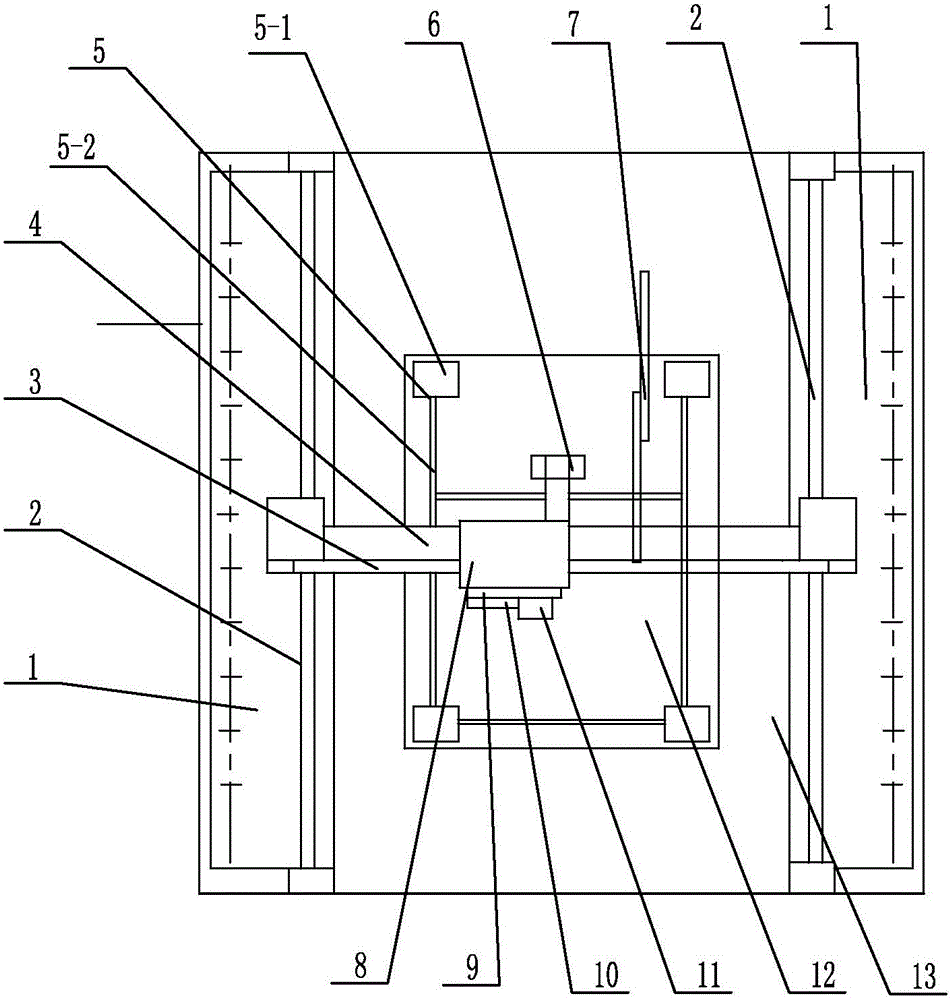
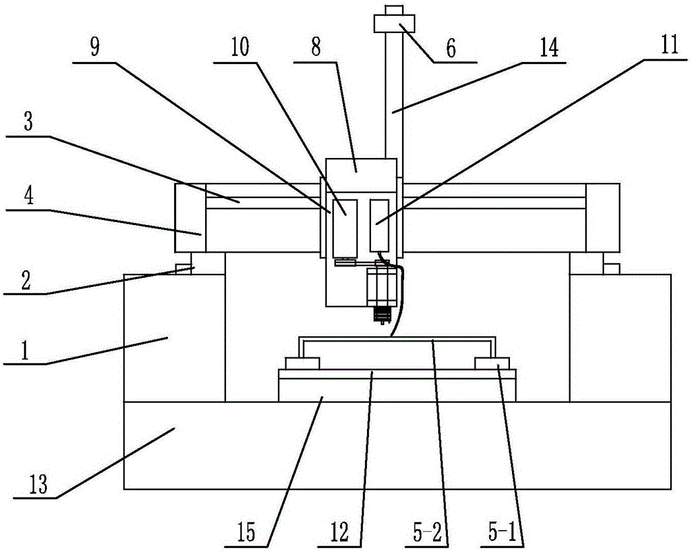
[0021] See Figure 1~3 Shown, the present invention is based on the machine vision LED light source positioning method of motor vehicle lights, according to the following steps.

[0022] (1) Transport the circuit board 12 fixed with the LED light source to the workbench 13 of the punching station, press and position it on the workbench 13 by the pressing block 5-1, so that the circuit board 12 is processed on the workbench 13 Can not move. The compression mechanism 5 of the present invention is installed on the workbench 13, and the briquetting block 5-1 of the compression mechanism is arranged around, and the briquetting block 5-1 is connected with the frame 5-2, and the frame 5-2 is connected with the cylinder. The frame 5-2 is driven to make multiple pressure blocks 5-1 act simultaneously, which is convenient for crimping the circuit board 12 on the workbench 13 or releasing the circuit board 12. See figure 2 As shown, the present invention can be provided with backing ...


PUM


Abstract

The invention relates to a motor vehicle lamp LED light source positioning method based on machine vision. The motor vehicle lamp LED light source positioning method based on machine vision comprises the steps that a circuit board where an LED light source is fixed is conveyed to a workbench on a punching station to be pressed and positioned, and a power supply module supplies working voltage to the circuit board to turn on the LED light source; and the image of the circuit board after the LED light source is turned on is collected by an industrial camera and loaded into an industrial personal computer, the industrial personal computer conducts light distribution analysis on the obtained position of the LED light source, the positions of all installation holes in the circuit board are determined and a signal is output according to the light distribution positions of the LED light source, a longitudinal driving mechanism and a transverse driving mechanism are started to move to punching positions, a vertical driving mechanism is started to drive a milling mechanism to move downwards along a vertical guide rail, the installation holes in the circuit board are milled, and meanwhile, and milling slag discharged in the milling process is sucked away in time through negative-pressure gas in a dust collection and filtration mechanism. According to the motor vehicle lamp LED light source positioning method based on machine vision, the positions of the installation holes in the circuit board can be determined according to the position of the LED light source after welding, and the light distribution performance of a whole vehicle is improved by improving the assembly precision.

Description

technical field [0001] The invention relates to a method for locating LED light sources of motor vehicle lights based on machine vision, and belongs to the technical field of automotive electronic vehicle lights. Background technique [0002] With the rapid development of automotive electronics, various car lights are applied to the whole car, among which LED car lights are not only numerous, but also have higher and higher requirements for car light distribution. The existing car lamp production method is to weld the LED light source on the circuit board, install the circuit board on the housing, and finally install the lampshade to meet the designed light distribution requirements. During the assembly process of the car lamp, the circuit board with the LED light source needs to be mounted on the housing for fixing, so the circuit board and the housing need to be processed with corresponding mounting holes, and finally fixed by fasteners or other methods. Now when the circ...

Claims


Application Information

Patent Timeline
IPC IPC(8): B23C1/06
CPCB23C1/06
Inventor 顾东超季鹤亭戴笠笠昌进孙书强
Owner CHANGZHOU XINGYU AUTOMOTIVE LIGHTING SYST
Why Eureka
Eureka Blog
Learn More