
Demounting and mounting device of valve lock clamp

A technology of valve lock clamp and cylinder head, which is applied in the direction of hand-held tools and manufacturing tools, which can solve the problem of poor positioning accuracy of disassembly and assembly devices, inability to meet the disassembly and assembly requirements of large quantities, high strength and high efficiency, and low work efficiency of personnel and other problems, to achieve the effect of high disassembly and assembly efficiency, reasonable structural design and easy realization

Active Publication Date: 2016-10-26
CHINA NORTH ENGINE INST TIANJIN
View PDF7 Cites 5 Cited by
  • Summary
  • Abstract
  • Description
  • Claims
  • Application Information

AI Technical Summary

Problems solved by technology

In the prior art, when removing and installing the valve lock clip of the cylinder head, three people are required to operate at the same time to complete the following operation steps: one person fixes the cylinder head, one person uses the single valve lock clip 10 removal tool to compress the valve spring 11, One person uses a magnetic bar or other tools to remove and install the valve lock clip 10. The positioning accuracy of the disassembly device is poor, the work efficiency of the personnel is low, and there are also personnel safety risks caused by loose tooling caused by operating errors or splashing of the lock clip.
[0005] Therefore, the existing method and device for disassembling and disassembling the valve lock clip can no longer meet the requirements of large-scale, high-strength, and high-efficiency disassembly and assembly, and it is necessary to develop a new type of valve lock clip disassembling device to meet the actual work requirements

Method used


Image

  • Demounting and mounting device of valve lock clamp
  • Demounting and mounting device of valve lock clamp
  • Demounting and mounting device of valve lock clamp

Examples


Embodiment Construction

[0030] It should be noted that, in the case of no conflict, the embodiments of the present invention and the features in the embodiments can be combined with each other.

[0031] The present invention will be described in detail below with reference to the accompanying drawings and examples.

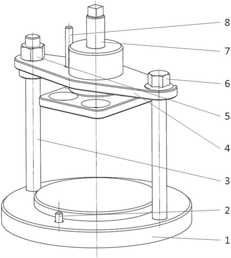
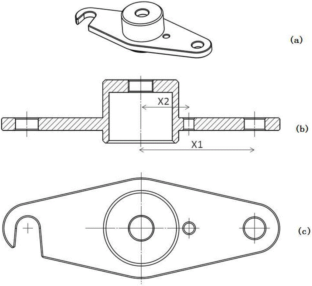
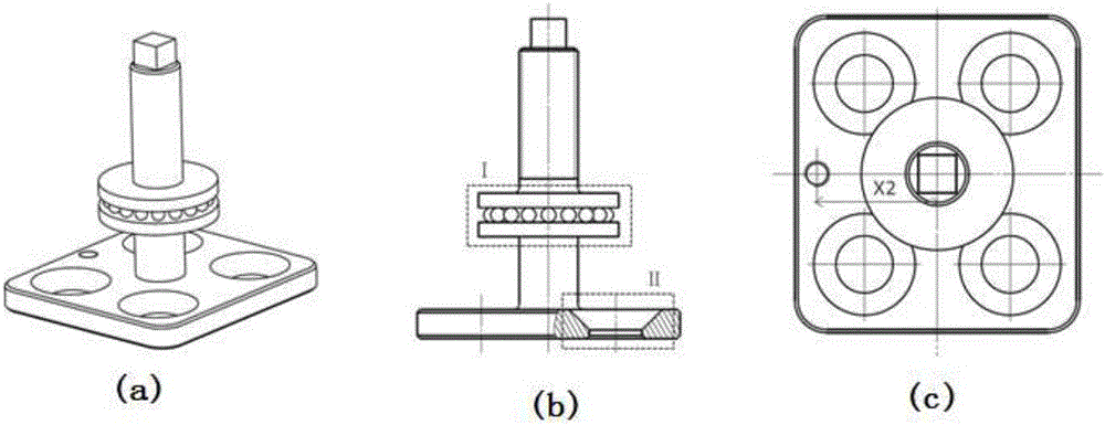
[0032] A valve lock clip disassembly device, such as Figures 1 to 3 As shown, it includes a base 1, a first positioning stud 3, a fixed pressing plate 4, a pressing bolt 6, a rotating pressing plate 7 and a second positioning stud 8,

[0033] The base 1 is provided with a positioning structure for disassembling the cylinder head with a positioning belt; the two ends of the fixed pressure plate 4 are respectively fixed on the base 1 through the first positioning stud 3 and the compression bolt 6;

[0034] The rotating platen 7 includes an upper threaded rod structure, a middle load-bearing structure and a lower bottom plate structure connected sequentially from top to bottom;

[0035] ...


PUM


Abstract

The invention provides a demounting and mounting device of a valve lock clamp. The demounting and mounting device comprises a base, a first locating stud, a fixed press plate, a compression bolt, a rotary press plate and a second locating stud. The two ends of the fixed press plate are fixed to the base through the first locating stud and the compression bolt correspondingly. The rotary press plate comprises a threaded rod structure on the upper portion, a bearing structure on the middle portion and a bottom plate structure on the lower portion from top to bottom, wherein the threaded rod structure, the bearing structure and the bottom plate structure are connected in sequence. The threaded rod structure is in threaded connection with the fixed press plate. A rotary mechanism is arranged in the middle of the bearing structure. A concave hole structure with the number corresponding to that of a valve with a demounting air cylinder cover is arranged on the bottom plate structure. The second locating stud penetrates the fixed press plate to be inserted in the bottom plate structure for locating. The demounting and mounting device has the following beneficial effects that large-scale, high-strength and high-efficiency demounting and assembling work of the valve lock clamp in the multi-valve air cylinder cover of an internal combustion engine can be met, and one-person operation can be achieved; and structural design is reasonable, implementation is easy, and demounting and mounting efficiency is high.

Description

technical field [0001] The invention belongs to the technical field of disassembly and assembly of engines, and in particular relates to a disassembly and assembly device for valve lock clips. Background technique [0002] The valve is one of the important parts of the engine's valve train. The working conditions are extremely harsh, and the working temperature of the valve head is very high. On the premise of optimizing the shape and reducing the movement quality, it is necessary to ensure sufficient strength, stiffness, heat resistance and resistance. grinding ability. The valve guide provides guidance for the up and down movement of the valve stem and is an important cooling channel for the valve. During its working process, through the suction of the valve and the expansion caused by the temperature rise, the oil can automatically enter the friction surface to lubricate; when the engine stops working, due to capillary action, the oil is sucked into the pores again, whic...

Claims


Application Information

Patent Timeline
IPC IPC(8): B25B27/24
CPCB25B27/24
Inventor 张强杨贵春李志鹏冯垣洁高云峰薛隆全齐国栋刘志刚
Owner CHINA NORTH ENGINE INST TIANJIN
Learn More