High-precision camera shooting measuring method for detecting sedimentation and pose of railway detecting vehicle

A technology for camera measurement and detection of vehicles, which is applied in the direction of railway vehicle shape measuring devices, railway car body parts, railway auxiliary equipment, etc., which can solve the problems of high measurement cost, heavy workload, and high maintenance cost of facilities, and achieve high measurement accuracy, fast effect

Active Publication Date: 2016-10-26
NAT UNIV OF DEFENSE TECH
View PDF9 Cites 22 Cited by
  • Summary
  • Abstract
  • Description
  • Claims
  • Application Information

AI Technical Summary

Problems solved by technology

This ground static measurement method has a long observation cycle, low efficiency, heavy workload, high measurement cost, and high facility maintenance cost. It is difficult to achieve continuous and high-frequency observation of bridge settlement, and cannot meet the needs of high-speed rail construction and operation and maintenance.
In terms of dynamic measurement equipment, the detection trolley that can measure the absolute offset of the line has low operating efficiency and relies heavily on the high-speed railway engineering measurement plane control network; the relatively fast track inspection vehicle and comprehensive inspection vehicle can only track relatively uneven, Absolute settlement of railway foundations cannot be detected

Method used


Image

  • High-precision camera shooting measuring method for detecting sedimentation and pose of railway detecting vehicle
  • High-precision camera shooting measuring method for detecting sedimentation and pose of railway detecting vehicle
  • High-precision camera shooting measuring method for detecting sedimentation and pose of railway detecting vehicle

Examples


Embodiment Construction

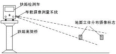
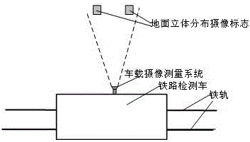
[0023] (1) Photogrammetry based on three-dimensional distribution marks

[0024] On the ground outside the railway, a plurality of camera measurement marks distributed in space are arranged. The relative relationship between the camera marks is known. By analyzing the imaging relationship between the marks on the image, the settlement and attitude parameters of the detection vehicle can be measured separately.

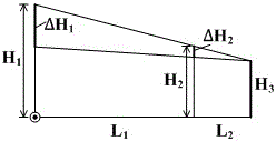
[0025] 1) Subsidence camera measurement based on three-dimensional distribution marks

[0026] Due to the shaking of the detection vehicle platform during dynamic measurement, the pointing and attitude of the vehicle-mounted camera measurement system will change, the three-dimensional distribution marks must be reasonably designed to measure the settlement of the detection vehicle, so that the measurement is basically not affected by the camera attitude, that is, the direction of the optical axis. The invention utilizes the characteristic that the relative relation of ...


PUM


Abstract

The invention provides a high-precision camera shooting measuring method for detecting the sedimentation and the pose of a railway detecting vehicle. The high-precision camera shooting measuring method comprises two implementation schemes, wherein the scheme I is a camera shooting measuring scheme based on three-dimensional distributed marks, a plurality of camera shooting measuring marks are spatially and three-dimensionally distributed on the ground next to the railway; the relative relationship between every two camera shooting marks is known; when a detecting vehicle travels and passes by a ground mark, an observing mark of a camera shooting measuring system mounted on a platform of the detecting vehicle is utilized, through analysis of a mark picture, the dynamic and high-accuracy measurement of the sedimentation and attitude parameters of the detecting vehicle is realized; the scheme II is a camera shooting measuring scheme based on a plane reflecting mirror; plane mirror facilities are arranged on the ground outside the railway; a camera imaging analyzing system and a point light source are mounted on the detecting vehicle; when the detecting vehicle travels and passes by the plane mirror facilities, image points of the vehicle-mounted camera shooting system in the plane mirror are shot and detected by utilizing the vehicle-mounted camera shooting system; through image analysis, the movement of the image points in the point light source in the plane mirror is measured; the altitude change of the platform of the detecting vehicle is calculated, and the sedimentation measuring of the railway foundation is realized.

Description

technical field [0001] The invention relates to the field of rail traffic dynamic monitoring and camera measurement, and in particular to a high-precision camera measurement method for the settlement and pose of a railway inspection vehicle. The invention sets camera signs on the ground and installs a camera measurement system on the inspection vehicle, achieving high precision Measure the settlement and pose of the railway inspection vehicle itself, and provide key technical support for high-precision dynamic measurement of railway track foundation settlement. Background technique [0002] The current method of railway foundation settlement measurement and monitoring is mainly ground static measurement. By using surveying and mapping instruments such as levels, range finders, theodolites, and total stations, the monitoring network datum points, working datum points, and settlement deformation points are established, and reference datums are introduced in sections. The eleva...

Claims


Application Information

Patent Timeline
Patent Type & Authority Applications(China)
IPC IPC(8): B61K9/08
CPCB61K9/08
Inventor 于起峰张红良尚洋张小虎杨夏
Owner NAT UNIV OF DEFENSE TECH
Why Eureka
Try Eureka