Turnover mechanism

A technology of overturning mechanism and rotating shaft, which is applied in the direction of conveyors, conveyor objects, transportation and packaging, etc. It can solve the problems of many manpower, affect production efficiency, and low efficiency, and achieve the goal of reducing manpower, improving production efficiency, and increasing moving speed Effect

Inactive Publication Date: 2016-10-26
黄建财
View PDF6 Cites 3 Cited by
  • Summary
  • Abstract
  • Description
  • Claims
  • Application Information

AI Technical Summary

Problems solved by technology

This process requires more manpower and is less efficient, which affects the overall production efficiency

Method used


Image

  • Turnover mechanism
  • Turnover mechanism

Examples


Embodiment Construction

[0014] The present invention will be described in further detail below in conjunction with the accompanying drawings.

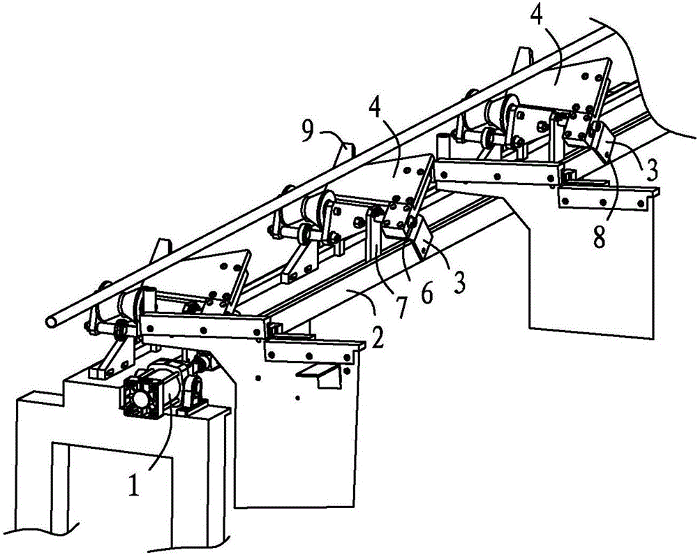
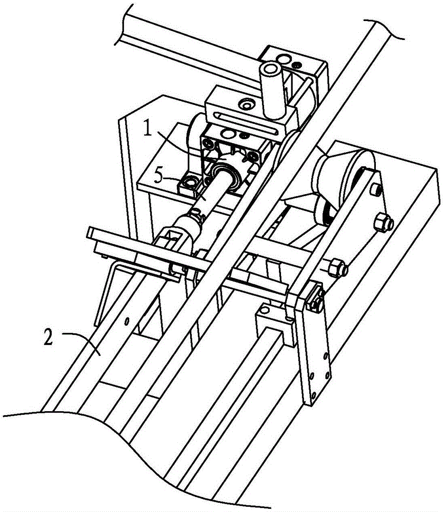
[0015] refer to figure 1 and figure 2 : Overturn mechanism, including cylinder 1, connecting rod 2, hinge arm 3 and swash plate 4, connecting rod 2 is connected with cylinder 1, connecting rod 2 and cylinder 1 are located on the same straight line, and one end of hinge arm 3 is arranged on connecting rod 2 , hinged with the connecting rod 2, the swash plate 4 is fixed on the hinge arm 3 by bolts, the cylinder 1 can drive the connecting rod 2 to move, and the angle between the swash plate 4 and the connecting rod 2 is less than 90°. Therefore, when the piston rod of the cylinder 1 stretches out, the piston rod pushes the connecting rod 2 to move forward.

[0016] The cylinder 1 is connected with the connecting rod 2 through a Y-shaped joint 5, one end of the Y-shaped joint 5 is connected with the piston rod of the cylinder 1, and the other end is fixed with...


PUM


Abstract

The invention discloses a turnover mechanism. The turnover mechanism comprises an air cylinder, a connecting rod, a hinge arm and an inclined plate. The connecting rod is connected with the air cylinder, the connecting rod and the air cylinder are located on the same straight line, one end of the hinge arm is arranged on the connecting rod and is hinged to the connecting rod, the inclined rod is fixed to the hinge arm, the air cylinder can drive the connecting rod to move, and the included angle between the inclined plate and the connecting rod is smaller than 90 degrees; and the air cylinder pushes the connecting rod to move, the hinge arm arranged on the connecting rod correspondingly rotates, and therefore the inclined plate fixed to the hinge arm correspondingly rotates, and a tube placed on the inclined plate can roll into a roller, and performing of the next working procedure is facilitated. Accordingly, the turnover mechanism can prevent the tube from being manually moved, manpower is reduced, the moving speed of the tube is improved, and the production efficiency is improved.

Description

technical field [0001] The invention belongs to the main components of a pipe feeding machine, in particular to a turning mechanism. Background technique [0002] When the existing pipe feeding machine is feeding, especially when feeding the pipe with a long length, after the pipe is conveyed to the required height, the pipe is often manually moved to the conveying roller, which is convenient for the roller to convey. One step processing. This process requires a lot of manpower, and the efficiency is low, which affects the overall production efficiency. Contents of the invention [0003] The object of the present invention is to provide a turning mechanism capable of solving at least one of the above-mentioned problems. [0004] According to one aspect of the present invention, a turning mechanism is provided, including a cylinder, a connecting rod, a hinge arm and a swash plate, the connecting rod is connected to the cylinder, the connecting rod and the cylinder are loc...

Claims


Application Information

Patent Timeline
IPC IPC(8): B65G47/82
CPCB65G47/82B65G2201/0276
Inventor 黄建财
Owner 黄建财
Why Eureka
Try Eureka