
Winding machine for the manufacture of lap spools and method for winding a lap

A technology of winding machine and lap, which is applied in the field of winding lap, can solve the problems of expensive structure and cost, and achieve the effect of lowering temperature level, reducing fuzziness, and avoiding sticking

Active Publication Date: 2017-10-17
TRUETZSCHLER GRP SE
View PDF2 Cites 0 Cited by
  • Summary
  • Abstract
  • Description
  • Claims
  • Application Information

AI Technical Summary

Problems solved by technology

The disadvantage associated with this is that the winding belt has to be replaced after it has been in operation for several months, which is very expensive
Furthermore, the guidance of the winding strip and the maintenance of a constant tension are structurally very complex, which cannot be compensated by a higher winding speed

Method used


Image

  • Winding machine for the manufacture of lap spools and method for winding a lap
  • Winding machine for the manufacture of lap spools and method for winding a lap
  • Winding machine for the manufacture of lap spools and method for winding a lap

Examples


Embodiment Construction

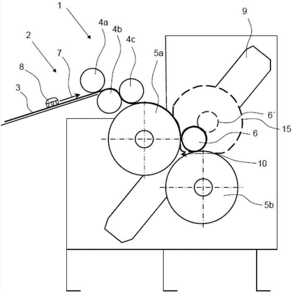
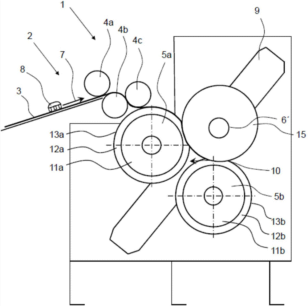
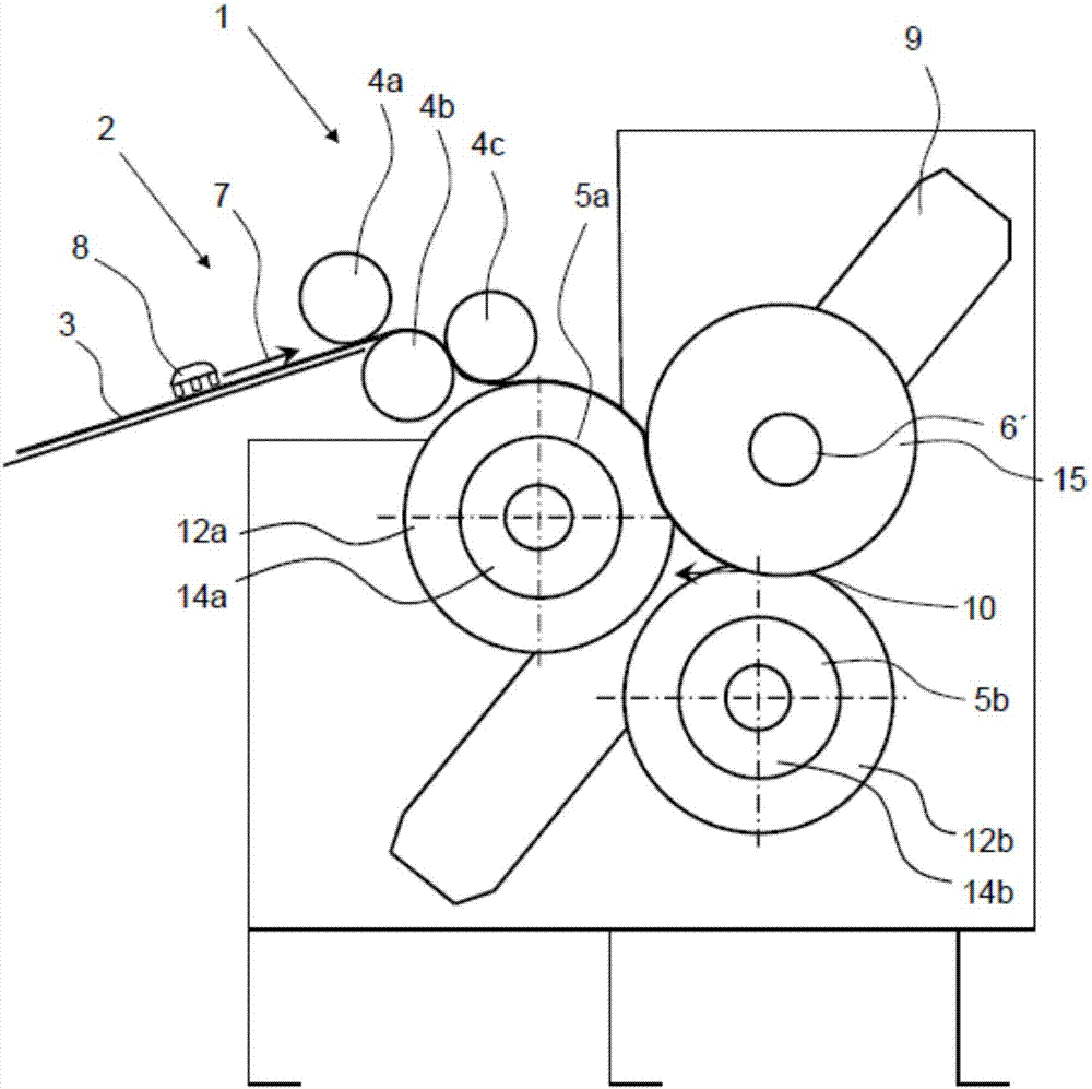
[0028] exist figure 1 The winder 1 is shown in the textile industry for example in the preparation of a combing shop How to use it according to the existing technology. A plurality of fiber ribbons 3 , which may be made of natural or man-made fibers, are conveyed through the cans of the winder 1 and stretched in a drafting device not shown. The fiber web 3 is guided further along the material flow direction 7 through the feed area 2 to a plurality of pressure rollers 4 a - 4 c which guide the fiber web 3 between the two winding rollers 5 a , 5 b and the winding sleeve 6 . Between the pull-in area for the production of cotton lap reels (Wattwickel). A precompressor 8 , which homogenizes the fiber strip 3 , can be arranged in or on the feed region 2 . Alternatively, the lap reel can also be produced between one or two winding rollers and a surrounding belt.

[0029] The winding sleeve 6 is clamped on its end side by two not shown side disks and runs along the guide rail 9 a...


PUM


Abstract

The invention relates to a winding machine which combines a plurality of fiber tapes with one another and stretching into cotton wool, wherein the formed cotton wool is wound into a cotton wool roll on the winding sleeve by means of two winding rollers or by means of at least one winding roller and a strip to be fed onto a combing machine. The invention is characterized in that the at least one winding roller has an elastic outer shell or an outer circumference.

Description

technical field [0001] The invention relates to a winding machine which combines several fiber strips together to form a lap and draws it, wherein the formed lap is formed on a winding sleeve by means of two winding rollers or by means of At least one winding roll and a strip are wound into lap spools for feeding to the comber. [0002] Furthermore, the invention relates to a method for winding a lap. Background technique [0003] The currently customary feeding of flat combs takes place via lap reels, which are previously produced from the individual belts in a winder. For this purpose, the winder takes the sample in the form of, for example, at least one section of 24 or 36 strips, wherein the sample is temporarily stored in a round or rectangular can. The strips are joined to each other in the winder and stretched slightly to form a lap. The lap is wound into a lap spool by means of a sleeve in a winding unit with at least two winding rollers, wherein the lap spool is ...

Claims


Application Information

Patent Timeline
Patent Type & Authority Patents(China)
IPC IPC(8): B65H18/20B65H19/30
CPCB65H18/20B65H19/30B65H2701/30D01G27/00
Inventor 阿米尼·莱德
Owner TRUETZSCHLER GRP SE
Learn More