
Integrated house wall structure

An integrated house and wall structure technology, applied in the field of integrated house wall structure, can solve the problems of poor wind and moisture proof effect, and achieve good thermal insulation effect, good enclosure effect, and good wind and moisture proof performance

Active Publication Date: 2018-12-25
重庆非屋装配式建筑技术有限公司
View PDF10 Cites 0 Cited by
  • Summary
  • Abstract
  • Description
  • Claims
  • Application Information

AI Technical Summary

Problems solved by technology

[0005] The present invention intends to provide an integrated house wall structure to solve the problem of poor windproof and moisture-proof effect of existing walls

Method used


Image

  • Integrated house wall structure
  • Integrated house wall structure
  • Integrated house wall structure

Examples


Embodiment 1

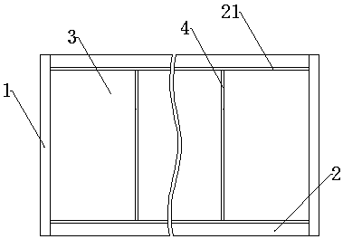
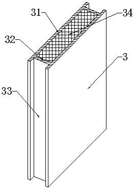
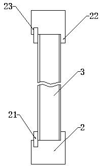
[0026] Embodiment 1, this embodiment is basically as attached figure 1 Shown: the wall structure of an integrated house, including columns 1, beams and rectangular plate-shaped walls; such as image 3 As shown, the crossbeam includes a crossbeam body 2, and a positioning platform 22 is integrally formed on the crossbeam body 2, and a positioning groove 23 is provided on the crossbeam body 2 on one side of the positioning platform 22, and a limit bar 21 is provided in the positioning groove 23, and the bottom of the wall The end is clamped and clamped between the two by the positioning table 22 and the limit bar 21, and the side end of the wall is detachably connected to the column 1. Such as figure 2 As shown, the wall includes several rectangular wall panels 3 with a length of 2000 mm and a width of 600 mm. The wall panels 3 include a frame and a thermal insulation layer 34; The oppositely arranged panel 31 and two side panels 32 between the two panels 31, the opposite sid...

Embodiment 2

[0028] Embodiment two, the difference between this embodiment and embodiment one is only that the size of wallboard 3 is long 2000 millimeters, the rectangular plate of wide 300 millimeters, and panel 31 is flat rectangular plate, as Figure 5 As shown, the side plate 32 is a special-shaped plate with a U-shaped cross section, and the panel 31 and the side plate 32 are connected and fixed by welding (welding is the preferred method used in this embodiment, and press-fitting, clipping, and bolting can also be used. , bonding, etc.). The size of the wall panel 3 set in this way can be applied to most transport vehicles, and is more convenient for handling; it is also more flexible in use, and when a small part needs to be replaced, only a small area needs to be replaced, which is more convenient. The contact area between the U-shaped side plate 32 and the panel 31 is larger, which can provide stronger support for the panel 31, and the formed wall panel 3 has better bending resis...


PUM


Abstract

The invention discloses an integrated building wall structure in the wall field of the building. The integrated building wall structure comprises standing posts, a cross beam, and a wall body. The bottom end of the wall body is connected to the cross beam; and the side ends of the wall body are connected to the standing posts. The wall body consists of a plurality of wallboards including frames and heat-preservation and insulation layers; each frame includes two panels and two side boards; each side board is fixed with two panels; and heat-preservation and insulation cavities and mounting grooves are encircled by the panels and the side boards. The mounting grooves formed in the each two adjacent wallboards are opposite to each other; a positioning bar is arranged between each two adjacent wallboards; windproof bars are arranged between the positioning bars and the side boards; and a T-shaped sealing bar is arranged at a joint between each two adjacent wallboards. According to the scheme, the integrated building wall structure has advantages of convenient installation and dismounting, low building cost, wide application range, stable and reliable structure, good waterproof and windproof performances, and good heat-preservation and insulation effect. Therefore, problems that the consumed time and labor costs are high, the heavy wall can not be moved conveniently, the windproof and moisture-proof performances are poor, and the heat-preservation and insulation capability is poor according to the existing wall body building process can be solved effectively.

Description

technical field [0001] The invention relates to the field of building walls, in particular to an integrated house wall structure. Background technique [0002] Body of wall is an important part of a building, and it is the main component in the vertical direction of the building. It is usually a building that is built with bricks and stones to form a roof or separate the inside and outside. The wall mainly plays the role of separation, enclosure and load bearing, as well as functions of heat insulation, heat preservation and sound insulation. [0003] At present, in order to ensure a better enclosure and load-bearing effect, fixed buildings are all made of masonry and concrete walls. This kind of wall is often a whole with one wall, and several bricks are piled up in sequence during construction. The construction is time-consuming and labor-intensive, and it is necessary to ensure that the entire wall is flat, which puts high demands on the construction workers. After the b...

Claims


Application Information

Patent Timeline
Patent Type & Authority Patents(China)
IPC IPC(8): E04B2/00E04C2/292E04C2/30E04B1/02
CPCE04B1/02E04B2/00E04C2/292E04C2/30
Inventor 罗昊
Owner 重庆非屋装配式建筑技术有限公司
Learn More