Composite rotor vacuum pump

A compound rotor and vacuum pump technology, applied in the direction of pumps, pump components, pump combinations for elastic fluid rotary piston type/swing piston type, etc., can solve problems such as high fuel consumption, complex structure, and large gear transmission noise, and achieve safety High performance, simplified transmission structure, and noise reduction effect

Inactive Publication Date: 2016-10-26
BEIJING LANGHE SCI & TECH LTD
View PDF7 Cites 8 Cited by
  • Summary
  • Abstract
  • Description
  • Claims
  • Application Information

AI Technical Summary

Problems solved by technology

[0003] The purpose of the present invention is to provide a composite rotor vacuum pump to solve the technical pr

Method used


Image

  • Composite rotor vacuum pump
  • Composite rotor vacuum pump
  • Composite rotor vacuum pump

Examples


Embodiment 1

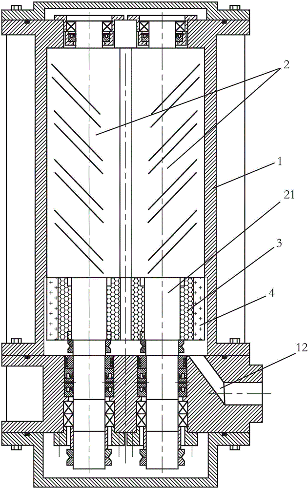
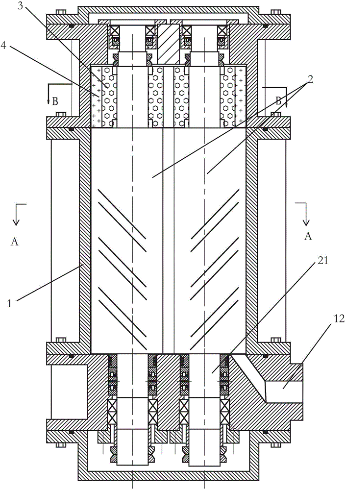
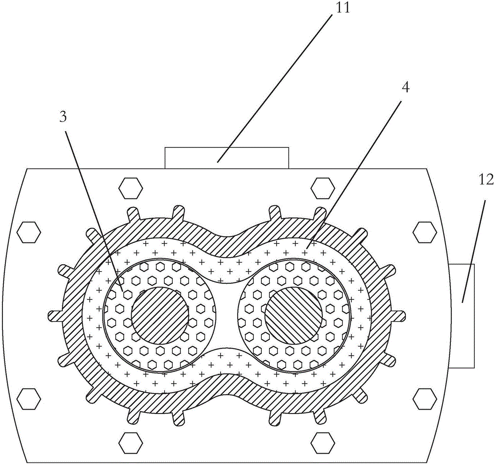
[0039] Such as Figure 1-4 Shown is a schematic structural view of the present invention applied to a screw dry vacuum pump; the specific technical solution is as described above. I won't repeat them here.

[0040] It works as follows:

[0041] The motor stator is energized, and the motor rotor on the rotor in the pump cavity forms an induced electromotive force after power is applied. Since the motor stator is a common one, the frequency of the two motor rotors is the same. The motor rotor will rotate at the same frequency, and drive the rotor in the pump chamber to rotate at high speed and reverse synchronously, which meets the requirements of the vacuum pump rotor shaft synchronously and mutually reversely rotating, replacing the traditional motor, coupling, gear set .

[0042] Thus, the traditional motor drives the gear set to drive the complex structure of the pump chamber rotor to rotate. The complexity of the structure is greatly reduced, and the manufacturing cost ...

Embodiment 2

[0045] Such as Figure 5-8 Shown is a schematic diagram of the structure of the application of the present invention to a Roots vacuum pump. Since it is also driven by double rotors, it is also applicable to the technical solution of the present invention. The specific technical solution is as described above, and will not be repeated here;

[0046] Applying the present invention to a Roots vacuum pump, its Roots rotor can be a two-lobe Roots rotor, a three-lobe or a four-lobe Roots rotor.


PUM


Abstract

The invention discloses a composite rotor vacuum pump. The composite rotor vacuum pump comprises a pump chamber and a rotor. The rotor comprises two rotor shafts synchronously rotating along opposite directions, two ends of the rotor shaft are supported through bearings at two ends in the pump chamber, the pump chamber is provided with an air inlet and an air outlet, the vacuum pump also comprises a motor rotor and a motor stator, the motor rotor is fixed to the rotor shaft, and a position in the pump chamber corresponding to the motor rotor is provided with the common motor stator. The motor stator and motor rotor drive the rotor shafts to rotate so that a structure is greatly simplified, a seal structure is simplified and equipment reliability is improved. The composite rotor vacuum pump solves the technical problem that the traditional vacuum pump has a complex structure, large gear driving noise and high oil consumption.

Description

technical field [0001] The invention relates to a composite rotor vacuum pump. Background technique [0002] At present, vacuum pumps are commonly used equipment in the industrial field. Roots vacuum pumps, claw dry vacuum pumps, and screw dry vacuum pumps are commonly used dual-rod vacuum pumps. The basic principles of the above-mentioned several vacuum pumps are the same, they are all driven by the motor and the gear set to rotate two of the rotating shafts, and the air is squeezed out through the upper meshing section to form a vacuum exhaust. However, there is a big problem in this way, because its structure is particularly complex and there are many sealing parts, so the reliability is low. During the transmission process, couplings and gears will cause a lot of energy consumption; during the operation of the gears, the mutual meshing will generate huge noise, and at the same time, vacuum pump oil is required for lubrication. The vacuum pump oil consumption is large, s...

Claims


Application Information

Patent Timeline
IPC IPC(8): F04C25/02F04C23/02
CPCF04C25/02F04C23/02F04C2240/40
Inventor 徐曦朱红梅
Owner BEIJING LANGHE SCI & TECH LTD
Why Eureka
Try Eureka