Pipeline leakage detection device and detection method

A leak detection device and leak detection technology, applied in pipeline systems, mechanical equipment, gas/liquid distribution and storage, etc., can solve problems such as complex signal acquisition and processing, and inconvenient sensor maintenance.

Inactive Publication Date: 2016-10-26
NINGBO XINGJIAN SPACE MACHINERY +1
View PDF8 Cites 31 Cited by
  • Summary
  • Abstract
  • Description
  • Claims
  • Application Information

AI Technical Summary

Problems solved by technology

After the sensor is buried, it is inconvenient to maintain, and the signal acquisition and processing are more complicated

Method used


Image

  • Pipeline leakage detection device and detection method
  • Pipeline leakage detection device and detection method
  • Pipeline leakage detection device and detection method

Examples


Embodiment Construction

[0037] The invention will be described in further detail below in conjunction with the accompanying drawings and specific embodiments.

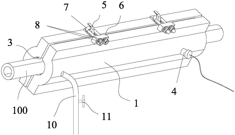
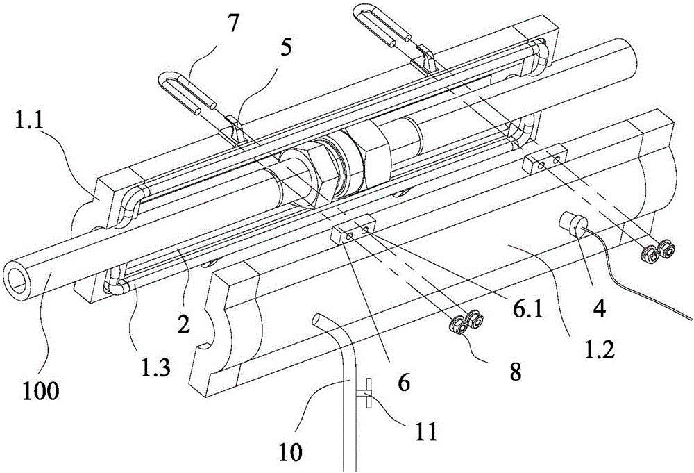
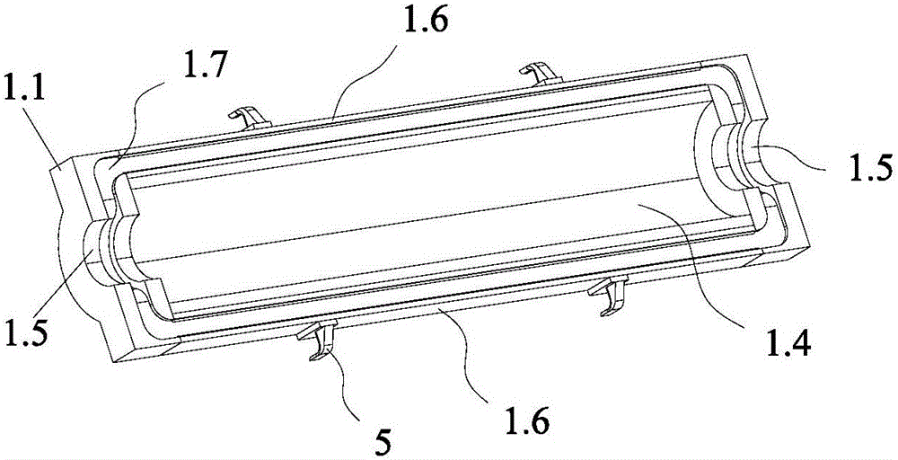
[0038] See attached figure 1 to attach Figure 8 As shown, a pipeline leakage detection device includes an inclusion 1 that wraps the pipeline section 100 to be tested and forms an annular seal; the inclusion 1 extends along the axis of the pipeline section 100 to be tested, and the inclusion 1 There is a space 2 for accommodating gas between the inner wall surface and the outer wall of the pipeline section 100 to be tested; through holes 3 for accommodating the pipeline section 100 to be tested are provided at both ends of the inclusion 1; the inclusion 1 and the pipeline section 100 to be tested are The through hole 3 is a sealed connection; the inclusion 1 is provided with a gas leakage sensing device 4 for monitoring whether the detected pipeline section 100 leaks; the gas leakage sensing device 4 is electrically connected to an external...


PUM


Abstract

The invention discloses a pipeline leakage detection device and detection method. The device comprises a wrapping body (1) which coats a detected pipeline segment (100) and forms annular sealing; the wrapping body (1) extends along the axis of the detected pipeline segment (100), and a space (2) for containing gas is reserved between the inner wall face of the wrapping body (1) and the outer wall of the detected pipeline segment (100); the two ends of the wrapping body (1) are provided with through holes (3) for containing the detected pipeline segment (100); a gas leakage induction device (4) for monitoring whether leakage is generated to the detected pipeline segment (100) or not is arranged on the wrapping body (1); and the gas leakage induction device (4) is electrically connected with an external controller. After the structure is adopted, the pipeline leakage detection device which can carry out gas leakage detection and alarming and discharge leaked gas to a designated place and meanwhile achieves whole-process monitoring of a pipeline connector, a weld joint and a whole pipeline is provided.

Description

technical field [0001] The invention relates to the technical field of pipeline detection, in particular to a pipeline leakage detection device and detection method. Background technique [0002] The usual pipeline or system airtight inspection is generally to check the airtightness of the welding or joint parts of the pipeline or system in the non-working state. Leakage method, differential pressure method, vacuum method, etc. However, the high-pressure pipeline in the working state is always in the state of replenishing air, and a small amount of leakage cannot be reflected by a small change in pressure. Therefore, none of the above methods is suitable for leakage monitoring of high-pressure pipelines in working conditions. [0003] Monitoring the leakage of the gas pipeline in the working state can be realized by using a gas leakage sensor according to the gas type. For example, a certain number of oxygen concentration sensors can be installed near the pipeline that may...

Claims


Application Information

Patent Timeline
Patent Type & Authority Applications(China)
IPC IPC(8): F17D5/02
CPCF17D5/02
Inventor 张海鑫祝绪东李建国
Owner NINGBO XINGJIAN SPACE MACHINERY
Why Eureka
Try Eureka