
Displacement calculation method of wind turbine blades based on three-dimensional shell finite element model

A wind turbine blade and displacement calculation technology, applied in the direction of calculation, design optimization/simulation, special data processing applications, etc., can solve the problem of the large number of degrees of freedom of the blade shell finite element model, the cumbersome modeling process of the blade shell model, and the finite element shell finite element model. Problems such as low modeling efficiency

Inactive Publication Date: 2016-10-26
NORTH CHINA ELECTRIC POWER UNIV (BAODING)
View PDF1 Cites 13 Cited by
  • Summary
  • Abstract
  • Description
  • Claims
  • Application Information

AI Technical Summary

Problems solved by technology

However, the modeling process of the blade shell model is cumbersome, especially it takes a lot of time to set the ply information of the shell elements, which leads to low modeling efficiency of the shell finite element model
In addition, the total number of degrees of freedom of the blade shell finite element model is too large to be efficiently used in the aeroelastic analysis of wind turbine multibody systems

Method used


Image

  • Displacement calculation method of wind turbine blades based on three-dimensional shell finite element model
  • Displacement calculation method of wind turbine blades based on three-dimensional shell finite element model
  • Displacement calculation method of wind turbine blades based on three-dimensional shell finite element model

Examples


example 1

[0083] Example 1 is the main girder of box-shaped blades made of isotropic materials.

[0084] The width and height of the isotropic material box blade main girder are 1.5m and 3m respectively, the thickness is 0.05m, and the length is 30m. The main beam of the box blade is made of steel, with an elastic modulus of 200GPa, a Poisson's ratio of 0.3, and a density of 7800kg / m 3 .

[0085] The three-dimensional shell finite element model of the main girder of the box-type blade constrained by the fixed end of the root established by the finite element ANSYS software, such as Figure 5 shown. Among them, in order to reduce the influence of the boundary effect, a section of beam element is coupled at the free end to apply the load, such as Image 6 shown.

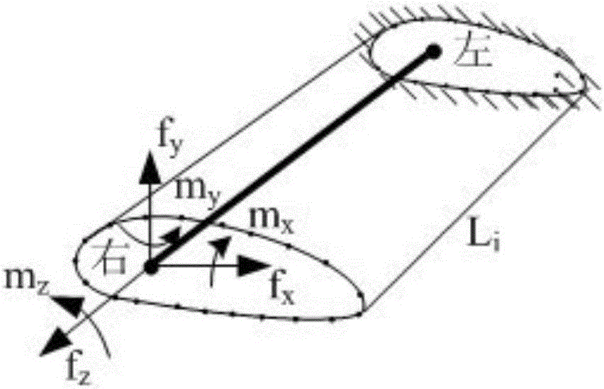
[0086] According to the method of the present invention, calculate and obtain the flexibility matrix C of each beam model, substitute into formula

[0087]

[0088] The stiffness matrix S of the beam model is obtained in...

example 2

[0101] Example 2 is the calculation of blade deformation of a 5MW wind turbine.

[0102] The 5MW wind turbine blade model established, the 5MW blade is composed of skin, spar cap and web, the blade length is 61.5m, and it is composed of 8 different airfoils, and the maximum chord length is 4.7m at the position near 20% .

[0103] Table 1 gives the mechanical properties of the composite materials used in the 5MW blades. The three-dimensional blade shell finite element model established by the shell99 element of ANSYS software is as follows: Figure 10 As shown, the displacement of the finite element model of the blade shell of the 5MW blade under the rated wind speed of 11.4m / s is calculated as Figure 11 shown.

[0104]

[0105] According to the displacement calculation steps, the displacement of the blade beam model of the 5MW blade under the rated wind speed of 11.4m / s is calculated, as shown in Figure 12. It can be seen from Figure 12 that under the wind speed of 11....


PUM

PropertyMeasurementUnit
Thicknessaaaaaaaaaa
Lengthaaaaaaaaaa
Elastic modulusaaaaaaaaaa

Abstract

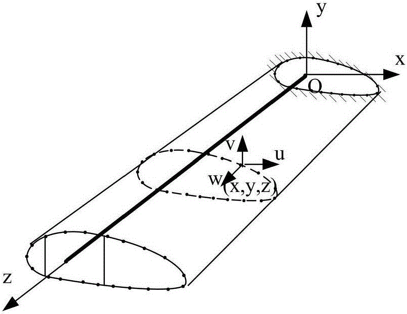
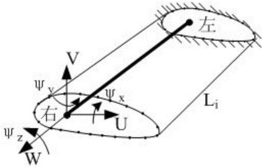
The invention discloses a displacement calculation method of wind turbine blades based on a three-dimensional shell finite element model. In the calculation method, a three-dimensional shell finite element model for blades is equivalent to beam models. The node of each beam model overlaps the reference center of a cross section. Blade roots are completely constrained. Six independent unit loads are applied to a free end of the shell finite element model. Based on the node displacement calculation method of a flexibility matrix of the beam model, flexibility matrixes of all beam models are solved for once. Without loads unknown, displacement of all pneumatic centers can be directly calculated so that calculation efficiency of blade elastic deformation during analyses and calculations of features including elasto-aerodynamic coupling for blades and bending-torsional coupling.

Description

technical field [0001] The invention relates to a wind turbine blade displacement calculation method based on a three-dimensional shell finite element-beam model, which is used to calculate the node displacement of the blade equivalent beam model, and is also used for displacement calculation and bending-torsion coupling characteristic calculation in aeroelastic analysis . Background technique [0002] Blade deformation is an important parameter for structural design and aeroelastic coupling analysis of wind turbine blades. Blade stiffness design requires accurate calculation of deformation; in aeroelastic coupling analysis, iterative calculation of blade deformation and aerodynamic performance is required. Therefore, calculating blade deformation accurately and quickly is an important issue in blade design. [0003] Wind turbine blades have the characteristics of large aspect ratio and aspect ratio, and are often simplified as a beam model. When the beam model is used for...

Claims


Application Information

Patent Timeline
IPC IPC(8): G06F17/50
CPCG06F30/17G06F30/23
Inventor 周邢银安利强
Owner NORTH CHINA ELECTRIC POWER UNIV (BAODING)
Learn More