Modeling realization method and system based on CAD

An implementation method and technology for implementing a system, which are applied in 3D modeling, 2D image generation, extraction from basic elements, etc., and can solve problems such as single function, inability to perform text calculations, and inability to quickly draw gears.

Inactive Publication Date: 2016-10-26
文小发
View PDF2 Cites 11 Cited by
  • Summary
  • Abstract
  • Description
  • Claims
  • Application Information

AI Technical Summary

Problems solved by technology

[0004] In view of the above-mentioned deficiencies in the prior art, the purpose of the present invention is to provide a CAD-based modeling implementation method and system, aiming to solve the problem that AutoCAD cannot draw formula curves, text calculations, and quickly draw gears in the prior art. Relatively single defect

Method used


Image

  • Modeling realization method and system based on CAD
  • Modeling realization method and system based on CAD
  • Modeling realization method and system based on CAD

Examples


Embodiment 1

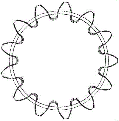
[0063] In AutoCAD, just load and run the gear.vlx command to automatically draw cylindrical gears in AutoCAD (either the cylindrical gear diagram can be drawn according to the length of the common normal line of the gear, or the gear diagram can be drawn according to the diameter of the pitch circle), AutoCAD automatically A cylindrical gear drawn as figure 2 shown. The demonstration program geardemo.vlx prints out the following information on the AutoCAD text window, and saves it in the file gear.txt at the same time.

[0064] Input parameters:

[0065] Law surface modulus Mn=3.0

[0066] End modulus Mt=3.10583

[0067] Number of gear teeth z=13

[0068] Pressure angle αn=20.0° of the law surface indexing circle

[0069] End surface indexing circle pressure angle αt=20.6469°

[0070] Addendum height coefficient han=1.0

[0071] Headspace coefficient cn=0.25

[0072] Helix angle β=15.0°

[0073] Gear root curve fillet coefficient kc=0.38

[0074] The normal surface ...

Embodiment 2

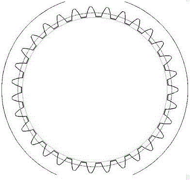
[0118] In AutoCAD, you only need to load and run the igear.vlx command to automatically draw the internal gear in AutoCAD. The internal gear automatically drawn by AutoCAD is as follows: image 3 shown. The demonstration program igeardemo.vlx prints out the following information on the AutoCAD text window and saves it in the file igear.txt.

[0119] Input parameters:

[0120] Law surface modulus Mn=3.0

[0121] End modulus Mt=3.10583

[0122] Number of gear teeth z=31

[0123] Pressure angle αn=20.0° of the law surface indexing circle

[0124] End surface indexing circle pressure angle αt=20.6469°

[0125] Addendum height factor han=1.0

[0126] Headspace coefficient cn=0.25

[0127] Helix angle β=15.0°

[0128] Internal gear root fillet coefficient kr=0.2

[0129] The normal surface displacement factor of the gear χn=0.2

[0130] Gear end face displacement factor χt=0.193185

[0131] Calculation results:

[0132] Gear addendum circle diameter da=92.8307

[0133] ...

Embodiment 3

[0166] In AutoCAD, you only need to load and run the z1z2.vlx command to automatically draw the external meshing gear pair in AutoCAD. The external meshing gear pair automatically drawn by AutoCAD is as follows: Figure 4 shown. The demonstration program z1z2demo.vlx prints out the following information on the AutoCAD text window, and saves it in the file z1z2.txt at the same time.

[0167] Input parameters:

[0168] Law surface modulus Mn=3.0

[0169] End modulus Mt=3.06702

[0170] Number of teeth z1=13

[0171] Number of teeth z2=37

[0172] Pressure angle αn=20.0° of the law surface indexing circle

[0173] End surface indexing circle pressure angle αt=20.4103°

[0174] Addendum height factor han=1.0

[0175] Headspace coefficient cn=0.25

[0176] Helix angle β=12.0°

[0177] Root curve fillet coefficient kc=0.38

[0178] Gear z1 tooth width B1=60.0

[0179] Gear z2 tooth width B2=55.0

[0180] Gear second tolerance group accuracy grade IT=7

[0181] Calculati...


PUM


Abstract

The invention discloses a modeling realization method and system based on CAD. The method comprises the steps of carrying out real-time detection on input parameters of a user when it is detected that a CAD application is operated; obtaining a drawing instruction in the input parameters, comparing and matching the drawing instruction with a pre-stored instruction library, and calling a drawing script corresponding to the drawing instruction when the matching is successful; and automatically drawing a corresponding model by operating the drawing script and the input parameters, and displaying the model. According to the method and the system, secondary development of AutoCAD is realized; and the CAD is enabled to have functions such as calculating a text file, carrying out value integration and value solution equation of a CAD expression, drawing a gear, carrying out line cutting, and designing and cutting garment and shoe paper patterns, thereby facilitating the user.

Description

technical field [0001] The invention relates to the technical field of mechanical drawing, in particular to a CAD-based modeling realization method and system. Background technique [0002] AutoCAD is a powerful drawing platform and the world's mainstream drawing software. However, AutoCAD only has the function of drawing, and it appears to be insufficient in the design process. There are many formula curves in the design process, AutoCAD cannot draw them, and secondary development is necessary, so that CAD has the function of drawing formula curves, CAD calculation of text files; numerical integration of CAD expressions and numerical solution of equations; the function of gears, lines Cutting function, clothing shoe pattern design and cutting function. [0003] Therefore, the prior art still needs to be improved and developed. Contents of the invention [0004] In view of the above-mentioned deficiencies in the prior art, the purpose of the present invention is to prov...

Claims


Application Information

Patent Timeline
Patent Type & Authority Applications(China)
IPC IPC(8): G06F17/50G06T11/20G06T17/00
CPCG06F30/367G06T11/203G06T17/00
Inventor 文小发
Owner 文小发
Why Eureka
Try Eureka