An external ejection type card feeding device of an automatic card issuing machine

An automatic card issuance and ejection technology, applied in computer parts, transmission record carriers, instruments, etc., can solve the problems of unsuitable direct transformation of existing card issuing machines, reducing the efficiency of crossing crossings, and slowing the speed of relay card transmission. Traffic efficiency, shortening the distance for taking the card, and the effect of small card taking damping

Active Publication Date: 2018-01-23
HEFEI UNIV OF TECH
View PDF9 Cites 0 Cited by
  • Summary
  • Abstract
  • Description
  • Claims
  • Application Information

AI Technical Summary

Problems solved by technology

For example, a "telescopic automatic card issuing machine" disclosed in the invention patent application with the publication number CN103810760A, although the card issuing machine can shorten the distance between the card issuing port and the card taker, the drive card conveying mechanism described in it is forward, The telescopic mechanism moving backward is a conventional screw drive mechanism, and the speed of relay card transmission is relatively slow. The card taker has to wait for the card to be released after pressing the button, which obviously reduces the traffic efficiency of the crossing.
In addition, the scheme of this invention patent application also has the following disadvantages: (1) This scheme moves the entire card conveying mechanism forward through the telescopic mechanism, and the internal structure of the card issuing machine is quite different from the existing card issuing machine, so it is not suitable for the existing card issuing machine. The card issuing machine is directly transformed; if the whole machine is replaced, not only the cost is high, but also the resources of the existing card issuing machine are greatly wasted; (2) the card is still tightly clamped by the conveying roller when it is at the card issuing port of the card conveying mechanism Hold, so there is also the disadvantage of large card removal damping

Method used


Image

  • An external ejection type card feeding device of an automatic card issuing machine
  • An external ejection type card feeding device of an automatic card issuing machine
  • An external ejection type card feeding device of an automatic card issuing machine

Examples


example 1

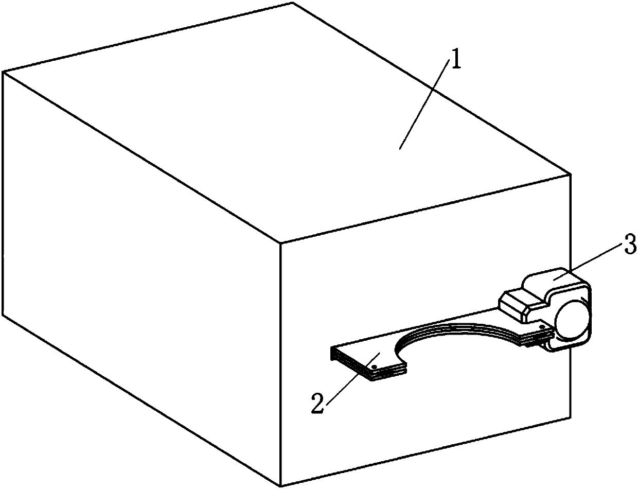
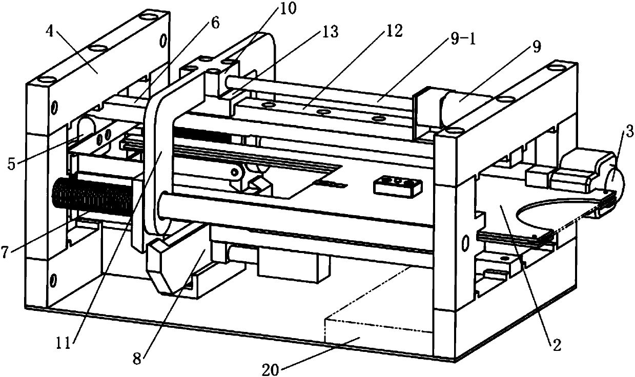
[0056] see Figure 1~3 , the card sending device in this example comprises frame 4, IC card ejector, card output box 2, the sensor that detects IC card, get card button 3 and controller 20; Described frame 4 is provided with shell 1 outside, and so The IC card ejector, the card output box 2, the sensor and the controller 20 that detect the IC card are all located in the shell 1.

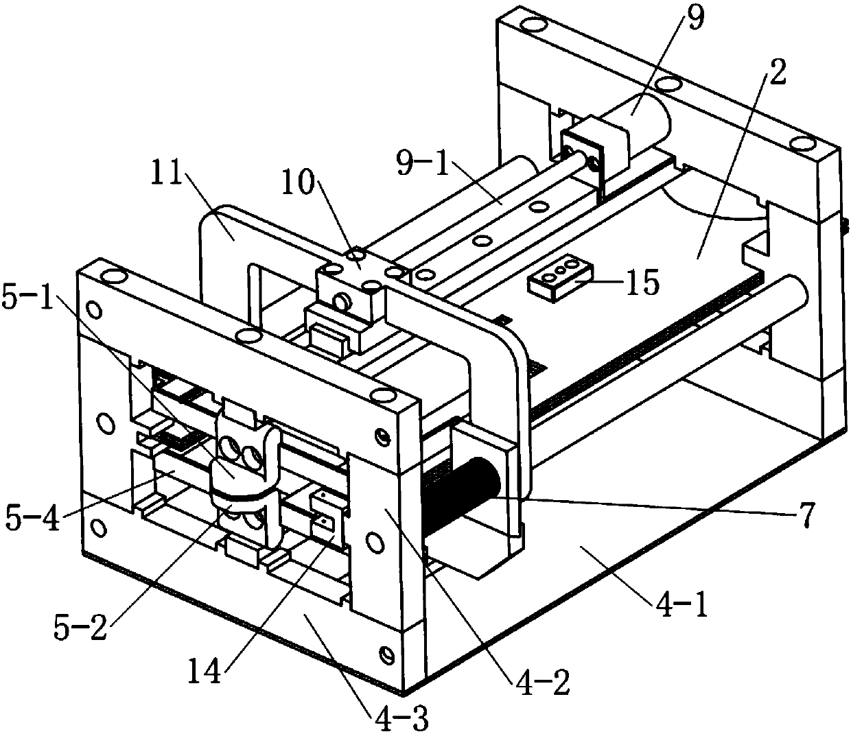
[0057] see Figure 2~3 , the frame 4 is composed of a base plate 4-1 and two rectangular support frames arranged at both ends of the base plate 4-1, wherein the rectangular support frame is composed of two support vertical plates 4-2 and two beams 4-3 surrounded.

[0058] see Figure 2-4 , the described IC card ejector is made up of holding caliper 5, pincer head constraint track 6 and energy storage ejection mechanism.

[0059] see Figure 5-8 , and combined with Figure 10 , 11 with figure 2 , the clamp head restraining track 6 is composed of an upper restraining track 6-1 and a lower rest...

example 2

[0087] see Figure 25 , the difference between the card feeding device in this example and Example 1 is:

[0088] The lower end of the connecting plate 7-3 and the push rod head of the electromagnetic push rod 8-3 are respectively provided with rollers 21;

[0089] When the connecting plate 7-3 moves from the throwing section c to the waiting section a and passes through the second slope 8-8, under the action of the second compression spring 8-5, the first The two inclined planes 8-8 always act on the rollers 21 provided at the lower end of the connecting plate 7-3;

[0090] Under the action of the second compression spring 8-5, the first slope 8-7 always acts on the roller 21 provided on the push rod head of the electromagnetic push rod 8-3.

[0091] Embodiments other than the above in this example are the same as Example 1.


PUM


Abstract

The invention discloses an externally connected ejection type card sending apparatus of an automatic card sender. The apparatus comprises a frame, an IC card ejector, a card discharging box, a sensor for detecting an IC card, and a card taking button, wherein the IC card ejector is composed of a card holding clamp, a binding clip constraint track and an energy storage ejection mechanism; the binding clip constraint track is composed of an upper constraint track and a lower constraint track which are parallel to each other at an upper position and a lower position, a constraint space with two wide ends and a narrow middle portion is formed between the two constraint tracks, and the constraint space is successively divided into a card waiting segment, a card holding segment and a card throwing segment along the length direction of the binding clip constraint track; the card holding clamp is clamped in the constraint space of the binding clip constraint track; the card discharging box is a flat box body fixed on the frame; the energy storage ejection mechanism is composed of an energy storage mechanism and an ejection switch, the energy storage mechanism comprises energy storage springs and a lead screw transmission mechanism, and the ejection switch comprises a bolt plate, a bolt seat and an electromagnetic push rod; and the card taking button is arranged at one side, close to an outlet, on the frame and faces a driveway.

Description

technical field [0001] The present invention relates to a device or device for collecting fares, tolls or entry fees at one or more administrative points, and in particular to a feeding device for cards. Background technique [0002] The unattended automatic card issuing machine is a device that is widely used in highway entrance passages, toll parking entrance passages, etc. for vehicle drivers to self-feed the card. The driver can obtain the pass card or parking card by himself by pressing the card withdrawal button. , without the need for staff to manually issue cards, which not only reduces the number of staff in these occasions, but also greatly improves the efficiency of vehicle traffic. [0003] The automatic card issuing machine is usually installed on the safety island of the crossing. In order to avoid scratches between the fuselage and the passing vehicles, the fuselage is usually retracted from the edge of the safety island by about 15cm during installation. The...

Claims


Application Information

Patent Timeline
Patent Type & Authority Patents(China)
IPC IPC(8): G07B15/06G06K13/08
CPCG06K13/0806G07B15/066
Inventor 王纯贤
Owner HEFEI UNIV OF TECH
Why Eureka
Try Eureka