Supercharge Your Innovation With Domain-Expert AI Agents!

A suspended surface mount fuse

A surface mount and fuse technology, applied in the field of electric power, can solve the problems of limited fuse length, space occupation, small fuse length, etc., and achieve the effects of preventing explosive damage, high anti-lightning characteristics, and explosion-proof volume

Active Publication Date: 2019-09-03
NANJING SART SCI & TECH DEV
View PDF9 Cites 0 Cited by
  • Summary
  • Abstract
  • Description
  • Claims
  • Application Information

AI Technical Summary

Problems solved by technology

However, the substrates in this design are all planar structures. Generally, the length of the fuse is equal to the length of the substrate. To detect a smaller current, it is necessary to increase the resistance of the fuse, thereby generating enough cohesive heat to fuse. The length limit can only be reduced by reducing the fuse wire diameter or using a higher resistivity fuse, which correspondingly reduces the fusing time and anti-lightning effect by 10 times, and increases the difficulty and cost of wire selection
In addition, such straight fuses are less effective against lightning strikes than curved fuses
[0004] On the basis of the above patents, the fuse can be pulled in a diagonal manner, so that the increased length of the fuse is very small, and the length of the substrate greatly limits the length of the fuse that can be used
If the glass fiber wire is used as the carrier, the fuse wire is wound on the glass fiber wire to form a melt, and the length of the fuse wire can be increased by increasing the number of turns of the fuse wire wound on the glass fiber wire, so that the overall diameter of the melt is biased. Large, but this method will cause the adhesive to be absorbed due to the capillary effect of the glass fiber thread during the hot pressing process of the substrate. On the one hand, the adhesive will decrease and affect the bonding strength between the substrate and the substrate. Introduction into the groove affects the contact of the arc extinguishing material with the melt in the groove and occupies the space in the groove

Method used


Image

  • A suspended surface mount fuse
  • A suspended surface mount fuse
  • A suspended surface mount fuse

Examples


no. 1 example

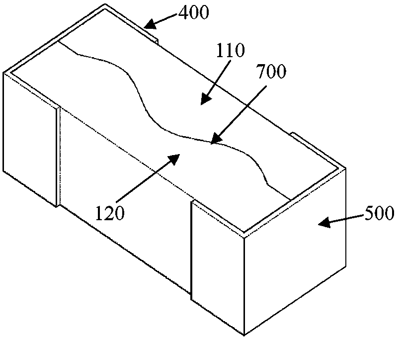
[0036] Such as figure 1 and figure 2 The shown suspended surface mount fuse includes an upper substrate 110 and a lower substrate 120 , and a fuse 310 is located between the upper substrate 110 and the lower substrate 120 . The upper substrate 110 and the lower substrate 120 assembled together are provided with terminal electrodes at the left and right ends, and the terminal electrodes include surface terminal electrodes 400 covering both ends of the upper surface of the upper substrate and both ends of the lower surface of the lower substrate and covering the upper and lower electrodes. The end electrodes 500 on the left and right end surfaces of the substrate, the surface end electrodes 400 and the end electrode 500 are structurally connected to form a "]"-shaped structure covering the ends of the upper and lower substrates, the end electrodes 500 and the fuse 310 It is electrically connected to the surface terminal electrode 400 .

[0037] The upper substrate 110 and the...

no. 2 example

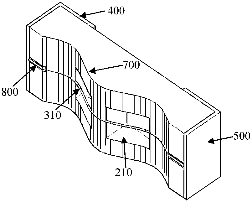
[0050] Such as Figure 8 As shown, on the basis of the first embodiment, both the upper substrate 110 and the lower substrate 120 are an assembly structure composed of an inner wall coating with a non-planar wave structure 700 and an outer cover plate, and the upper substrate 110 is composed of an upper The cover plate and the upper inner wall coating 910 are formed, the lower substrate 120 is composed of the lower cover plate and the lower inner wall coating 920, the upper surface of the upper inner wall coating 910 is closely attached to the lower surface of the upper cover plate, and the lower inner wall coating The lower surface of the layer 920 is close to the upper surface of the lower cover plate, the shape of the upper inner wall sticker 910 and the lower inner wall sticker 920 are in conformity with the non-planar wave structure 700, and the fuse 310 passes between the upper inner wall sticker 910 and the lower inner wall sticker 920. Pass. Different from the first e...

no. 3 example

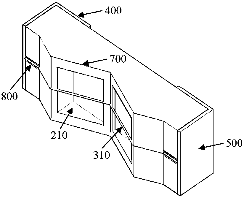
[0061] Such as Figure 9 As shown, on the basis of the first embodiment, the width of the non-planar wave structure 700 is set to be smaller than the width of the abutting surface of the upper substrate 110 and the lower substrate 120 .

[0062] This embodiment can also be improved on the basis of the second embodiment, and a rectangular groove is provided on the inner surface of the upper cover plate and the lower cover plate, and the width of the upper inner wall sticker 910 and the lower inner wall sticker 920 is smaller than the rectangular groove Width, put the upper inner wall sticker 910 and the lower inner wall sticker 920 into the rectangular grooves of the upper cover and the lower cover respectively, that is, stick together to form the upper substrate 110 and the lower substrate 120 .


PUM


Abstract

The invention relates to a novel suspension surface mounting fuse. The novel suspension surface mounting fuse comprises an upper substrate, a lower substrate, a fuse wire arranged between the upper and the lower substrates, and end portion electrodes arranged at left and right ends of the upper and lower substrates, wherein butt surfaces of the upper and lower substrates are respectively provided with a groove, and the fuse wire passes through the grooves. The novel suspension surface mounting fuse is characterized in that the butt surfaces of the upper and lower substrates are respectively provided with a non-planar fluctuation structure, the non-planar fluctuation structures of the upper and lower substrates are consistent in shape, and the fuse wire passes through the non-planar fluctuation structures. The novel suspension surface mounting fuse can be used for realizing overcurrent fusing protection in a smaller-current circuit and further has advantages of high lightning stroke prevention characteristic, explosion prevention characteristic and tiny volume.

Description

technical field [0001] The invention belongs to the technical field of electric power, and in particular relates to a fuse. Background technique [0002] The surface mount overcurrent fuse has the characteristics of small size and convenient installation. When the current in the circuit exceeds the safe value used by the equipment, the fuse in the surface mount overcurrent fuse connected in series in the circuit will be damaged due to overcurrent. Fuse due to high fever, and the circuit is disconnected in time to avoid damage to electrical equipment in the circuit. However, when the surface mount overcurrent fuse is developed to a small size, the fuse in the fuse cavity is easy to touch the inner wall of the shell material, which will easily cause the heat generated by the fuse under the overcurrent to be absorbed by the shell material. Absorbed away, the temperature of the fuse cannot reach the melting temperature in time, which increases the reaction time of the fuse or e...

Claims


Application Information

Patent Timeline
Patent Type & Authority Patents(China)
IPC IPC(8): H01H85/046H01H85/08H01H85/12H01H85/18
Inventor 南式荣朱鹏
Owner NANJING SART SCI & TECH DEV
Features
  • R&D
  • Intellectual Property
  • Life Sciences
  • Materials
  • Tech Scout
  • Unparalleled Data Quality
  • Higher Quality Content
  • 60% Fewer Hallucinations
Learn More