
Multifunctional temporary suspension device of distribution network for uninterruptible operation

A suspension device, multifunctional technology, applied in the direction of overhead line/cable equipment, etc., can solve problems such as wire slippage and bending

Active Publication Date: 2016-10-26
NANYANG POWER SUPPLY COMPANY OF STATE GRID HENAN ELECTRIC POWER
View PDF13 Cites 3 Cited by
  • Summary
  • Abstract
  • Description
  • Claims
  • Application Information

AI Technical Summary

Problems solved by technology

[0008] In view of this, the purpose of the present invention is to address the deficiencies of the prior art and provide a multifunctional temporary suspension device for non-stop operation of the distribution network, which can not only firmly fix the wires to prevent the problems of wire slippage and serious bending, but also has a simple structure and is easy to use. Removing and hanging, while reducing the labor intensity of the operators and increasing the safety of the operation

Method used


Image

  • Multifunctional temporary suspension device of distribution network for uninterruptible operation
  • Multifunctional temporary suspension device of distribution network for uninterruptible operation
  • Multifunctional temporary suspension device of distribution network for uninterruptible operation

Examples


Embodiment 1

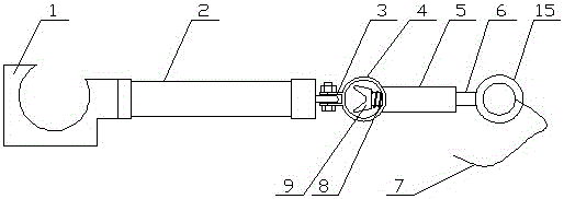
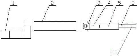
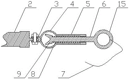
[0032] Such as figure 1 , figure 2 , image 3 As shown, the multifunctional temporary suspension device for non-stop operation of the distribution network includes an insulating rod 2, a wire hook 1 is provided at the left end of the insulating rod 2, and a temporary hanging point member is hinged at the right end of the insulating rod 2, and the temporary hanging point member includes a barrel shaped accommodating cavity 4, the ear plate 3 arranged on the left side of the accommodating cavity 4, the tube body 5 arranged on the right side of the accommodating cavity 4, and the elastic locking wire member arranged inside the tube body 5 , the temporary hanging point member is hinged to the right end of the insulating rod 2 through the ear plate 3;

[0033] The elastic locking wire member includes a locking wire rod 6, a grooved locking block 9 arranged on the left end of the locking wire rod 6, arranged on the right end surface of the locking block 9 and sleeved on the locki...

Embodiment 2

[0038] Such as Figure 4 , Figure 5 As shown, the multifunctional temporary suspension device for non-stop operation of the distribution network includes an insulating rod 2, a wire hook 1 is provided at the left end of the insulating rod 2, and a temporary hanging point member is hinged at the right end of the insulating rod 2, and the temporary hanging point member includes a barrel shaped accommodating cavity 4, the ear plate 3 arranged on the left side of the accommodating cavity 4, the tube body 5 arranged on the right side of the accommodating cavity 4, and the elastic locking wire member arranged inside the tube body 5 , the temporary hanging point member is hinged to the right end of the insulating rod 2 through the ear plate 3;

[0039] The elastic locking wire member includes a locking wire rod 6, a grooved locking block 9 arranged on the left end of the locking wire rod 6, arranged on the right end surface of the locking block 9 and sleeved on the locking wire rod...

Embodiment 3

[0045] Such as Image 6 , Figure 7 As shown, the multifunctional temporary suspension device for non-stop operation of the distribution network includes an insulating rod 2, a wire hook 1 is provided at the left end of the insulating rod 2, and a temporary hanging point member is hinged at the right end of the insulating rod 2, and the temporary hanging point member includes a barrel shaped accommodating cavity 4, the ear plate 3 arranged on the left side of the accommodating cavity 4, the tube body 5 arranged on the right side of the accommodating cavity 4, and the elastic locking wire member arranged inside the tube body 5 , the temporary hanging point member is hinged to the right end of the insulating rod 2 through the ear plate 3;

[0046] The elastic locking wire member includes a locking wire rod 6, a grooved locking block 9 arranged on the left end of the locking wire rod 6, arranged on the right end surface of the locking block 9 and sleeved on the locking wire rod ...


PUM


Abstract

The invention discloses a multifunctional temporary suspension device of a distribution network for uninterruptible operation. The multifunctional temporary suspension device comprises an insulating rod, wherein a wire hook is arranged at the left end of the insulating rod; a temporary suspension point member is arranged at the right end of the insulating rod and comprises a cylindrical accommodating cavity body, a lug plate arranged at the left side of the accommodating cavity body, a tube body arranged at the right side of the accommodating cavity body and an elastic wire locking member arranged in the tube body; the temporary suspension point member is hinged with the right end of the insulating rod through the plug plate; the elastic wire locking member comprises a wire locking rod, a locking block, an elastic part and an insulated flexible pull body; the locking block is arranged at the left end of the wire locking rod and is provided with a groove; the elastic part is arranged on the right end surface of the locking block and sleeves the wire locking rod; and the insulated flexible pull body is arranged at the right end of the wire locking rod. By the multifunctional temporary suspension device, a wire can be firmly fixed to solve the problems that the wire slips off and is seriously bent; the multifunctional temporary suspension device is simple in structure and easy to take and suspend; meanwhile, the labor intensity of an operator is reduced; and the operation safety is improved.

Description

technical field [0001] The invention belongs to the technical field of electric power maintenance equipment, and in particular relates to a multifunctional temporary suspension device for distribution network non-stop operation. Background technique [0002] The electric power industry is a basic industry of the national economy and a leading industry in the development of the national economy. Electric energy has been widely used in various sectors of the national economy and in all aspects of people's lives, and with the continuous development of my country's economic construction, urban construction has put forward stricter requirements for uninterruptible electric energy and voltage fluctuations. Industrial progress and automation Development, the improvement of people's living standards, and the popularization of household appliances have made improving the reliability of power supply an important task for the current power sector. Even if the power supply is interrupted...

Claims


Application Information

Patent Timeline
IPC IPC(8): H02G1/02
CPCH02G1/02
Inventor 罗杨瑞杨峰高辉王新运王健刘小克邓晨佳李文征陈庆岩
Owner NANYANG POWER SUPPLY COMPANY OF STATE GRID HENAN ELECTRIC POWER
Learn More