
a cable joint

A technology of cable joints and cable wires, which is applied in the direction of cable joints, etc., can solve the problems of cumbersome and complicated manufacturing processes, unstable working conditions, irregular shapes, etc., and achieve considerable social and economic benefits, great promotion and application value, and stable working conditions Effect

Active Publication Date: 2018-04-20
常德威迪电气有限责任公司
View PDF6 Cites 0 Cited by
  • Summary
  • Abstract
  • Description
  • Claims
  • Application Information

AI Technical Summary

Problems solved by technology

Moreover, in the connection mode of this structure, the contact area of ​​the wire is small, that is, the conductive cross-sectional area is small, the joint is prone to heat, and the working state is unstable; the production and construction process is cumbersome and complicated. Bolts are fastened one by one, especially epoxy resin needs to be poured on site, so it is affected by the ambient temperature, humidity and construction site (such as too much rain and humidity, snow or too low temperature can not be constructed, etc.), sometimes directly affect the progress of the project; volume Too large and irregular in shape, so it takes up a lot of space and affects the overall appearance of the indoor and outdoor installation.

Method used

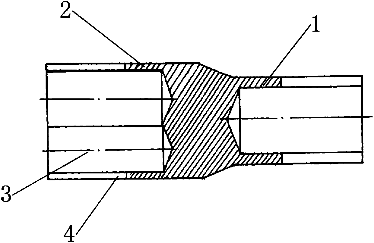

Image

  • a cable joint
  • a cable joint
  • a cable joint

Examples


Embodiment Construction

[0045] Embodiments of the present invention are described in detail below, and examples of the embodiments are shown in the drawings, wherein the same or similar reference numerals denote the same or similar elements or elements having the same or similar functions throughout. The embodiments described below by referring to the figures are exemplary and are intended to explain the present invention and should not be construed as limiting the present invention.

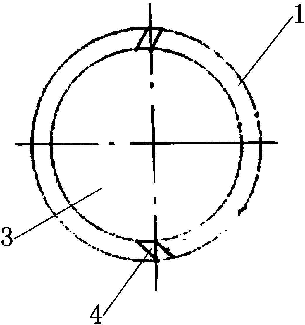
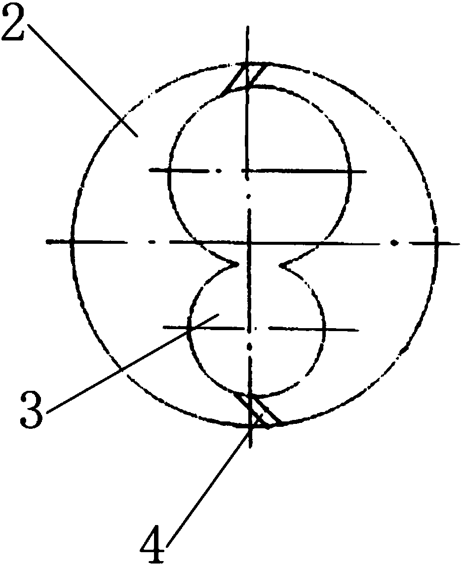
[0046] The cable joint provided by the present invention includes a connection body having a first connection end 1 and a second connection end 2, and the ends of the first connection end 1 and the second connection end 2 are respectively provided with at least one cable hole 3 in the axial direction , when the number of cable holes 3 at any connecting end is greater than one, the cable holes 3 at the extra ends of the first connecting end 1 or the second connecting end 2 communicate with each other. The ends of the fi...


PUM


Abstract

The invention relates to a cable connector. The cable connector comprises a connection body having a first connection end and a second connection end, wherein end portions of the first connection end and the second connection end are respectively provided with at least one cable hole axially, the cable holes are mutually communicated when the quantity of the cable hole of any connection end is greater than 1, the end portions of the first connection end and the second connection end are respectively provided with two skewed slots axially, and each skewed slot is communicated with the cable wire holes and an outer side wall of the connection body. The cable connector is advantaged in that the structure is simple, a conductive sectional area is large, stable work state and high versatility are realized, and the manufacturing and mounting process is effectively simplified.

Description

technical field [0001] The invention relates to the technical field of power cable design, and in particular relates to a cable joint. Background technique [0002] The existing cable joints generally use bolts to fasten the pressure plate to connect the two cable heads together, and pour epoxy resin on the outside of the joint for insulation. One incoming line of a phase cable is formed by one or several outgoing lines. A large T-shaped joint, and three-phase four-wire has four T-shaped joints, the larger the diameter of the wire, the larger the volume of the joint. Moreover, in the connection mode of this structure, the contact area of ​​the wire is small, that is, the conductive cross-sectional area is small, the joint is prone to heat, and the working state is unstable; the production and construction process is cumbersome and complicated. Bolts are fastened one by one, especially epoxy resin needs to be poured on site, so it is affected by the ambient temperature, humi...

Claims


Application Information

Patent Timeline
Patent Type & Authority Patents(China)
IPC IPC(8): H02G15/18
CPCH02G15/18
Inventor 高建民高碧寒
Owner 常德威迪电气有限责任公司
Learn More