A cell handover method and optical line terminal

A technology of optical line terminal and cell handover, applied in the field of communication, can solve problems such as communication interruption

Active Publication Date: 2019-09-20
CHINA UNITED NETWORK COMM GRP CO LTD +2
View PDF4 Cites 0 Cited by
  • Summary
  • Abstract
  • Description
  • Claims
  • Application Information

AI Technical Summary

Problems solved by technology

[0004] In this way, the use of PON to carry the wireless services of the micro base station will cause a large amount of signaling interaction due to frequent cell handover by the UE, forming a signaling storm, which will put a huge pressure on the core network and also cause the risk of communication interruption

Method used


Image

  • A cell handover method and optical line terminal
  • A cell handover method and optical line terminal
  • A cell handover method and optical line terminal

Examples


Embodiment 1

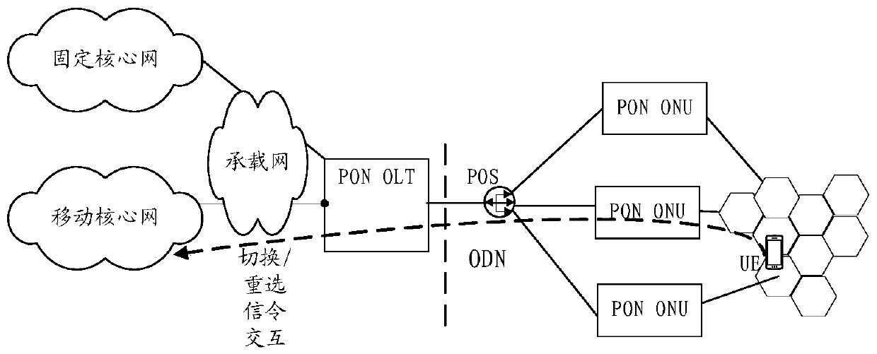
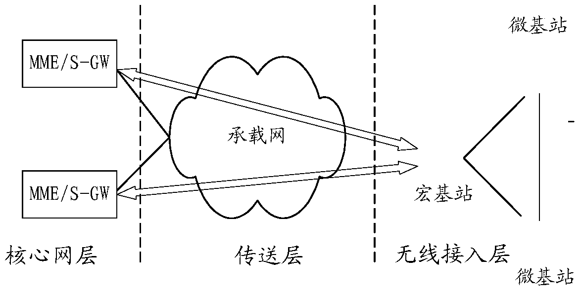
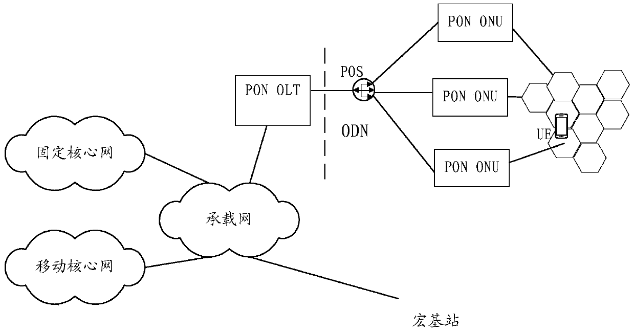
[0084] refer to figure 2 , figure 1 , after the PON bears the backhaul service of the micro base station, the 4G / LTE network structure can be as follows image 3 As shown, the macro base station directly performs backhaul services with the core network through the bearer network, and the micro base station performs service backhaul with the core network through the PON.

[0085]In a specific implementation, a control and management module is added in the optical line terminal to control wireless access and manage the local downband base station of the optical line terminal, that is, the micro base station that is connected to the optical line terminal. The control management module acts as an agent for the optical line terminal to manage the micro base stations in the area covered by the optical line terminal, and is responsible for managing the local downband base stations. In a specific implementation, the control management module records the network information of all l...

Embodiment 2

[0129] An embodiment of the present invention provides a cell handover method, taking a local downband base station in which both a source base station and a destination base station are optical line terminals as an example. refer to Figure 5 , the cell switching method provided by the embodiment of the present invention includes the following steps:

[0130] 401. The UE establishes a connection with an optical line terminal through a source Femtocell.

[0131] The connection here can be a voice connection or a data connection. The downband base stations of the optical line terminal are all under the PON, and the sequence of the uplink is UE-micro base station-ONU-OLT.

[0132] 402. The source Femtocell determines that the UE satisfies a cell handover condition according to the radio link state of the UE.

[0133] In a specific implementation, the source micro base station uses the existing wireless signal measurement, judgment strategy and algorithm to judge the wireless ...

Embodiment 3

[0153] An embodiment of the present invention provides a cell handover method, taking a local downband base station where the source base station is a macro base station and the destination base station is an optical line terminal as an example. refer to Figure 6 , the cell switching method provided by the embodiment of the present invention includes the following steps:

[0154] 501. The source macro base station determines that the UE satisfies a cell handover condition according to the radio link state of the UE.

[0155] In addition, the source macro base station will also send a handover command to the UE.

[0156] 502. The source macro base station notifies the core network device to send a first data transmission suspension instruction, instructing the core network device to suspend data transmission to the source macro base station.

[0157] Wherein, the core network device may be MME / S-GW.

[0158] In addition, the source macro base station will also send the buff...


PUM


Abstract

The present invention provides a cell switching method and an optical line terminal, and relates to the communication field. In a scene of using a passive optical network (PON) to bear a return business of a micro base station, and when a UE switches the cells, the signaling interaction of switching or reselection among the UE, the base station and a core network is avoided, thereby substantially reducing the number of the signaling interaction, and relieving the burdens of the core network. The cell switching method comprises the steps of using the optical line terminal to receive a migration demand message; according to the identifiers of a source base station and a destination base station, querying a pre-stored base station management table, and determining whether the switching of the UE is a local relevant switching business; recording the identifiers of all local lower band base stations in the base station management table, and using the local lower band base stations to carry out the return businesses with the core network equipment via the optical line terminal; if the optical line terminal determines that the switching of the UE is the local relevant switching business, forwarding the migration demand message to the destination base station, so that the destination base station is convenient to distribute wireless channel resources to the UE.

Description

technical field [0001] The invention relates to the communication field, in particular to a cell switching method and an optical line terminal. Background technique [0002] In recent years, mobile communication services have developed rapidly, 3G networks have been widely used, and 4G networks have also been rapidly developed. Mobile data services have become the focus of mobile communication business development. At this stage, most residential and commercial buildings have realized the speed-up of optical fiber broadband based on PON (Passive Optical Network, Passive Optical Network). Add PON-related network equipment to the network architecture. specifically, figure 1 A network architecture for PON to carry micro base station services, wherein the ONU (Optical Network Unit, Optical Network Unit) in the PON network is located at the user end and is used to carry the wireless services of micro base stations, which will save a lot of fiber usage and greatly Significantly...

Claims


Application Information

Patent Timeline
Patent Type & Authority Patents(China)
IPC IPC(8): H04W36/00H04W36/02H04Q11/00
Inventor 李家京刘建平杜伟赵卫临
Owner CHINA UNITED NETWORK COMM GRP CO LTD
Why Eureka
Try Eureka