
Exposure device and method for inspecting the same

A technology of exposure device and light source device, which is applied in the direction of lighting device, optics, light source, etc., and can solve the problem that it is difficult to identify whether the lamp is genuine or not

Active Publication Date: 2016-10-26
PHOENIX ELECTRIC CO
View PDF3 Cites 6 Cited by
  • Summary
  • Abstract
  • Description
  • Claims
  • Application Information

AI Technical Summary

Problems solved by technology

However, even if defective products can be detected by this method, it is difficult to identify whether the lamp is genuine or not

Method used


Image

  • Exposure device and method for inspecting the same
  • Exposure device and method for inspecting the same
  • Exposure device and method for inspecting the same

Examples


Embodiment 1

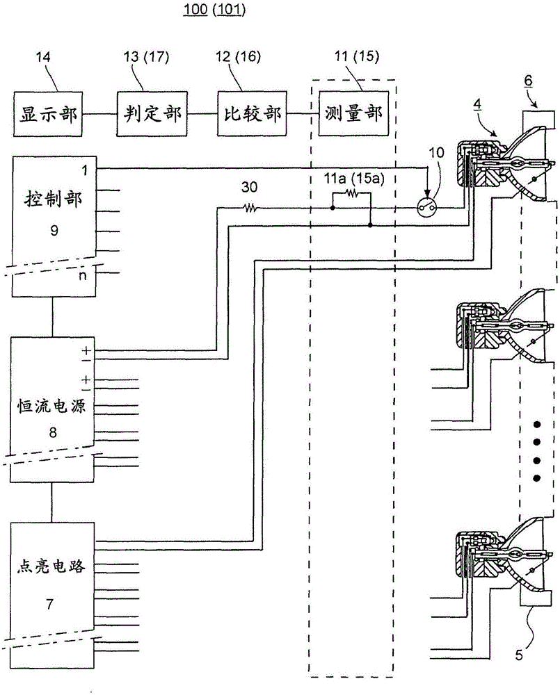
[0031] exist figure 1 In this case, when the power switch of the exposure apparatus 100 is turned on, the lighting circuit 7 supplies power to all the discharge lamps 1 . Usually, it takes several minutes for the discharge lamp 1 to start up completely. Immediately after the power switch of the exposure apparatus 100 is turned on, the control unit 9 turns on the first switch 10 connected to the first incandescent lamp 2 in the light source device 4 to supply a constant current from the constant current power supply 8 . After a predetermined time (for example, after 10 seconds) from the conduction of the first switch 10, the voltage across the first incandescent lamp 2 is measured by the measuring part 11, and the result is sent to the comparing part 12, and the comparing part 12 compares the The result and the voltage distribution ranges of a plurality of incandescent lamps for authentic product detection registered in the comparison unit 12 in advance will be sent to the det...

Embodiment 2

[0037] exist figure 1 Among them, the elements different from those in Example 1 are the measurement unit 15 (the internal resistance is the resistance 15a), the comparison unit 16, and the determination unit 17, and the other elements are the same. Description of the same elements as those in Embodiment 1 is omitted. Immediately after the exposure device 101 turns on the power switch, the first switch 10 connected to the first incandescent lamp 2 in the light source device 4 is turned on to supply a constant current from the constant current power source 8 . Immediately thereafter, the first measurement of the voltage across the first incandescent lamp 2 is performed by the measurement unit 15 , and the result is sent to the comparison unit 16 . Then, after a predetermined time (for example, after 10 seconds) from the first measurement, the second measurement of the voltage across the first incandescent lamp 2 is carried out by the measurement part 15, and the result is sent...


PUM


Abstract

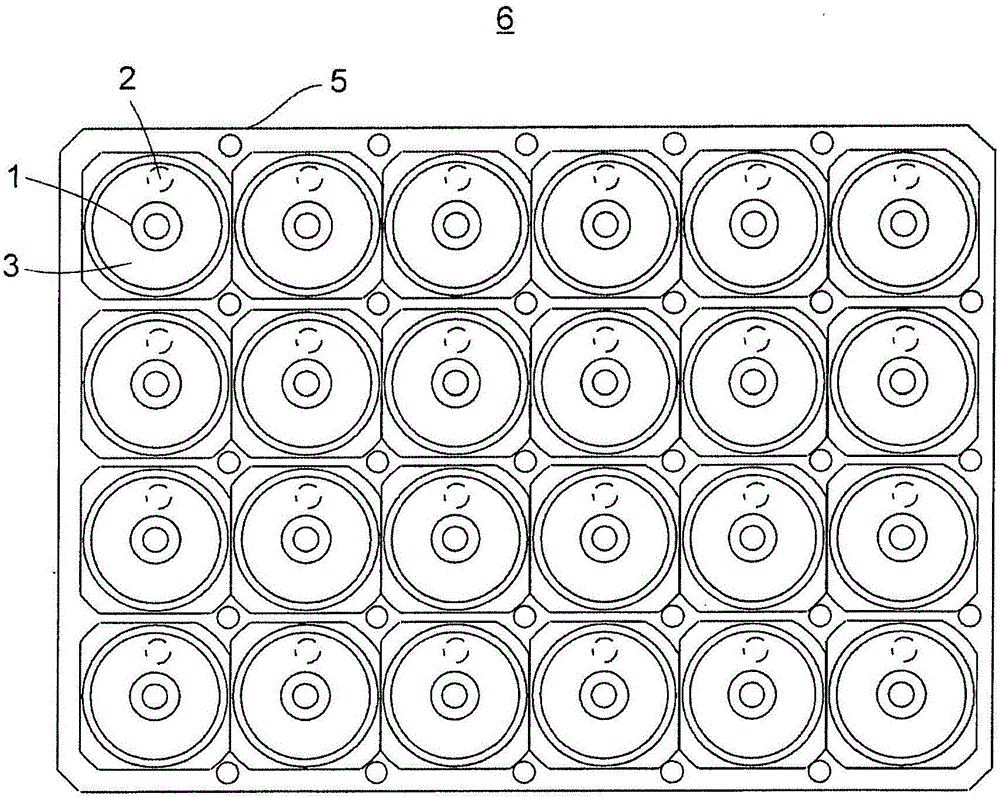
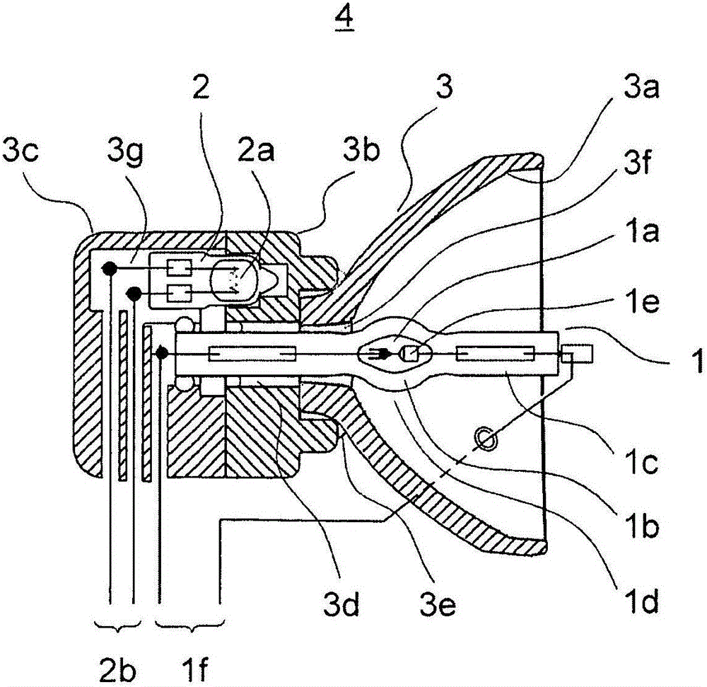
The invention provides an exposure device capable of inspecting whether a discharge lamp as a light source is a quality product or not in exposure apparatus such as a printed wiring substrate and a method for inspecting the exposure device. The exposure device (100) includes: one or more light source devices (4) including discharge lamps (1), a filament lamps (2) and a reflector containers (3); a frame (5) for installing the light source devices (4); a constant current power supply (8) for supplying current to the filament lamps (2); a switch (10) for turning on-off the current from the constant current power supply (8); a control unit (9) for turning on-off the switch (10) during a designated period; a measurement unit (11) for measuring the voltage of the filament lamps (2); a comparison unit (12) for comparing the voltage and a specified voltage range; a determination unit (13) for using the comparison result to determine if the discharge lamps (1) are quality products or not; and a display unit (14).

Description

technical field [0001] The present invention relates to an exposure apparatus for exposing printed wiring boards and the like, including an incandescent lamp for detecting whether a discharge lamp as a light source is a genuine product, and an inspection method thereof. Background technique [0002] Conventionally, a printed wiring board in which a metal such as copper is used to form a wiring pattern on a substrate made of resin or glass epoxy is used for mounting components on electronic equipment. Photolithography is used to form wiring patterns on these printed wiring boards. In this method, a photoresist as a photosensitive chemical is applied to the entire surface of a substrate on which a metal layer serving as wiring is formed, and irradiation light from an exposure device is irradiated through the same photomask as the wiring pattern. Among the photoresists, there are negative type photoresists in which the solubility of the photoresist is lowered by irradiation of...

Claims


Application Information

Patent Timeline
IPC IPC(8): H05B37/03
CPCG01R31/24H05B47/20G03F7/2004G03F7/70008G03F7/70016G03F7/70591G03F7/7065
Inventor 谷田敏昭
Owner PHOENIX ELECTRIC CO
Learn More