Printing mechanism of page printing machine

A technology of printing mechanism and printing machine, which is applied in the field of printing mechanism of sheet printing machine, can solve the problems such as the reduction of the printing quality of the sheet to be printed and the limitation of the printing speed of the inkjet head, so as to reduce the time not used for printing, improve Printing effect, effect of reducing invalid time

Inactive Publication Date: 2016-11-02
HEIDELBERGER DRUCKMASCHINEN AG
View PDF11 Cites 3 Cited by
  • Summary
  • Abstract
  • Description
  • Claims
  • Application Information

AI Technical Summary

Problems solved by technology

Improve the efficiency of digital printing presses by increasing the rotary printing speed, however this is limited by the printing speed of the inkjet head
And as the speed increases, the printing quality of the pages to be printed will decrease

Method used


Image

  • Printing mechanism of page printing machine
  • Printing mechanism of page printing machine
  • Printing mechanism of page printing machine

Examples


Embodiment Construction

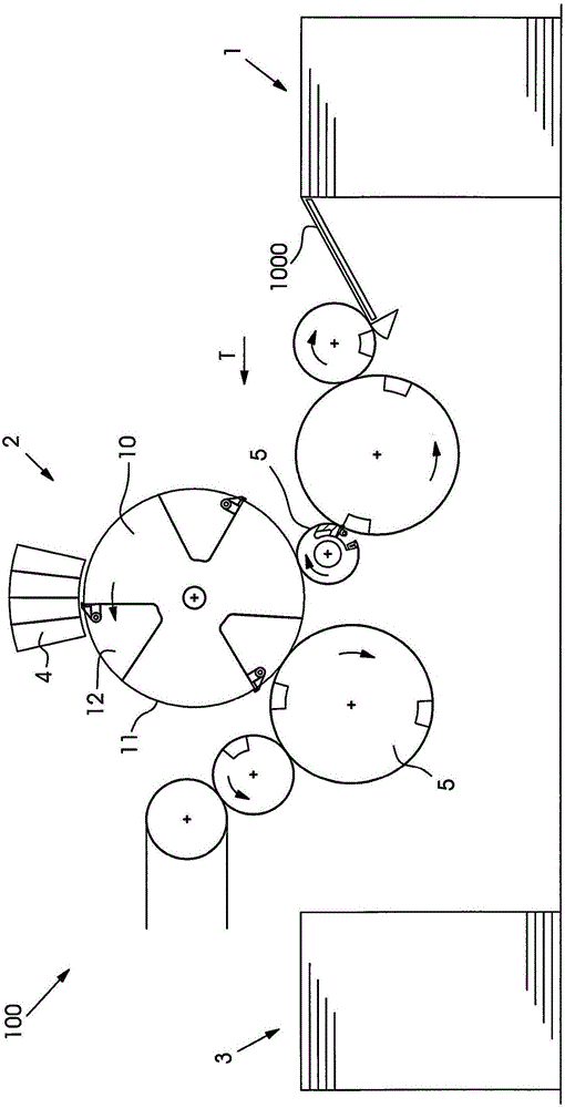
[0024] figure 1 Shown is a sheet printing press 100 , which is designed as a digital printing press. Each sheet 1000 is conveyed from the feeder 1 along the conveying direction T through the printing mechanism 2 to the stacker 3 . Here, the individual sheets 1000 are transported primarily by means of cylinders (ie a plurality of transport cylinders 5 and a printing cylinder 10 ). Arranged above the printing cylinder 10 are inkjet heads 4 which print a sheet 1000 which is moved past the printing cylinder 10 at small intervals. The printing cylinder 10 is therefore also referred to as a jetting cylinder.

[0025] In the embodiment shown, the printing cylinder 10 has three sheet holding areas 11 which are each separated from one another by a channel 12 .

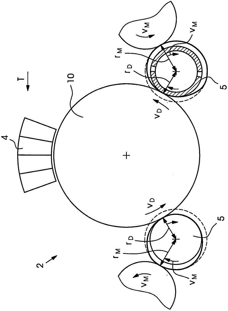
[0026] figure 2 A printing unit 2 according to the invention is shown in . The printing unit 2 has: a forward transfer cylinder 5 , a printing cylinder 10 , and a rear transfer cylinder 5 . The transport rollers 5 each h...


PUM


Abstract

The present invention relates to a printing mechanism (2) for a page printing machine (100). The printing mechanism (2) has a printing drum (10), a front transfer roller (5) and a rear transfer drum (5). According to the invention, the transfer drum (5) has a device (50) for stopping or accelerating the page. The device (50) has at least one substantially radially movable gripper bridge (51), so that the tangential velocity of the gripper bridge (51) can be varied and thus the tangential direction of pages (1000) speed can also be changed. The pages (1000) can be conveyed at a relatively low speed and at a relatively small distance from each other during the printing process by means of such a printing mechanism, thereby ensuring high printing quality and high printing efficiency. The invention also relates to the page printing machine (100) having such a printing mechanism.

Description

technical field [0001] The invention relates to a printing unit of a sheet printing machine with the features of the preamble of claim 1 and to a sheet printing machine with the features of claim 9 . Background technique [0002] The use of digital printing presses is known for printing sheets made of paper, cardboard and cardboard in small runs or with individual printing themes. When using the inkjet head to print the sheets, the individual sheets are moved under the inkjet head with a minimum distance by the conveying system. Revolving conveyor belts (eg designed as suction belts) and rotating rollers (so-called spray rollers) or revolving trays are known as conveyor systems, as described for example in US Pat. No. 8,579,286 B2. [0003] In a printing press solution using a cylinder, such as that described in US020090284561A1, a plurality of inkjet printing heads are arranged above the jetting cylinder, and these inkjet printing heads print a sheet which, relative to the...

Claims


Application Information

Patent Timeline
Patent Type & Authority Applications(China)
IPC IPC(8): B41F21/10B41J11/24B41J13/22B41J13/03B41J13/00B41J13/02
CPCB41F21/10B41J11/24B41J13/00B41J13/02B41J13/03B41J13/22B41J11/04B41J13/0009
Inventor S·穆沙尔
Owner HEIDELBERGER DRUCKMASCHINEN AG
Why Eureka
Try Eureka