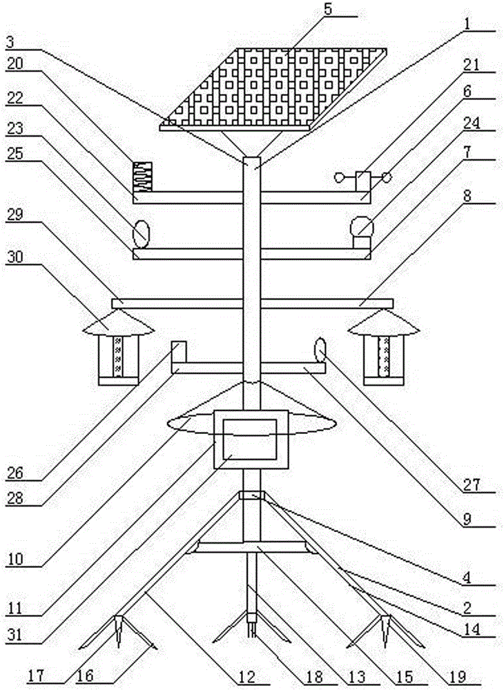
Solar farmland environment monitoring device
A technology of environmental monitoring and solar energy, applied in the direction of measuring devices, instruments, etc., can solve the problems of inconvenient use, single function, and inability to comprehensively monitor farmland environmental information, and achieve the effect of simple use, simple operation, and rich functions
- Summary
- Abstract
- Description
- Claims
- Application Information
AI Technical Summary
Problems solved by technology
Method used
Image
Examples
Embodiment 1
[0019] As shown in the figure, a solar farmland environment monitoring device includes a bracket 1, the bracket 1 is composed of a triangular support frame 2 and a support rod 3, the bottom end of the support rod 3 is connected to the triangular support frame 2 through a fixed ring 4, The solar collector plate 5 is installed on the top of the support rod 3, the first detection device 6 is installed on the upper end of the support rod 6, the second detection device 7 is installed on the lower end of the first detection device 6, and the second detection device 7 is installed on the lower end of the second detection device 7. The disinsection device 8, the third detection device 9 is installed at the lower end of the disinsection device 8, the protective cover 10 is installed at the lower end of the third detection device 9, and the control box 11 is installed at the lower end of the protective cover 10.
Embodiment 2
[0021] As shown in the figure, the tripod 2 is composed of a first support leg 12, a second support leg 13, and a third support leg 14, and the first support leg 12, the second support leg 13, and the third support leg 14 Connected by a fixed plate 15, the left and right sides of the bottom of the first support leg 12, the second support leg 13, and the third support leg 14 are equipped with fixed brackets 16, and the bottom of the first support leg 12 is equipped with soil Humidity sensing probe 17, soil salinity sensing probe 18 is installed in the middle of the bottom end of the second supporting leg 13, and soil pH value sensing probe 19 is installed in the middle of the bottom end of the third supporting leg 14.
Embodiment 3
[0023] As shown in the figure, the first detection device 6 is composed of a lightning protection device 20, a wind and rain sensor 21, and a first support cross arm 22, and the first detection device 6 is connected to the support rod 3 through the first support cross arm 22, so The lightning protection device 20 is installed on the left top of the first support cross arm 22 , and the wind and rain sensor 21 is installed on the right top of the first support cross arm 22 .
PUM
 Abstract
Description
Claims
Application Information
 - R&D
- Intellectual Property
- Life Sciences
- Materials
- Tech Scout
- Unparalleled Data Quality
- Higher Quality Content
- 60% Fewer Hallucinations
Browse by: Latest US Patents, China's latest patents, Technical Efficacy Thesaurus, Application Domain, Technology Topic, Popular Technical Reports.
© 2025 PatSnap. All rights reserved.Legal|Privacy policy|Modern Slavery Act Transparency Statement|Sitemap|About US| Contact US: help@patsnap.com

