Supersonic measuring sensor for water meter, heat meter and flowmeter and using method of sensor

A measurement sensor and ultrasonic sensor technology, applied in the fields of sensing and acoustics, can solve the problems of long installation length, inconvenient operation, moving parts, etc., and achieve the effect of small installation size, favorable for instrument measurement, and reduced volume

Active Publication Date: 2016-11-02
HUIZHONG INSTR
View PDF20 Cites 0 Cited by
  • Summary
  • Abstract
  • Description
  • Claims
  • Application Information

AI Technical Summary

Problems solved by technology

[0002] At present, the measurement of the liquid flow or heat in the existing pipeline is to install the ultrasonic sensor in the measuring pipe section, and measure the liquid flow or heat in the pipeline through ultrasonic detection technology; the installation form of the ultrasonic water meter, heat meter and flow meter measurement sensor is mainly There are two types: flange connection form and clip-on form. During the use of these two installation forms, the measurement sensor has the following problems: the measurement sensor installed in the flange connection form, because it involves the operation space of the flange connection, Therefore, its structure is complex, its shape is large, its installation length is long, its operation is inconvenient, and its cost is high; the measurement sensor installed in the form of a clip needs to lock the rotatable ultrasonic sensor after installation, and there are moving parts, installation In addition, the cost is high; for example: Chinese patent number: 201420273092.6, patent name: a card-type ultrasonic fluid flow measurement device, which is a measurement sensor installed in the form of a clip

Method used


Image

  • Supersonic measuring sensor for water meter, heat meter and flowmeter and using method of sensor
  • Supersonic measuring sensor for water meter, heat meter and flowmeter and using method of sensor
  • Supersonic measuring sensor for water meter, heat meter and flowmeter and using method of sensor

Examples


Embodiment 1

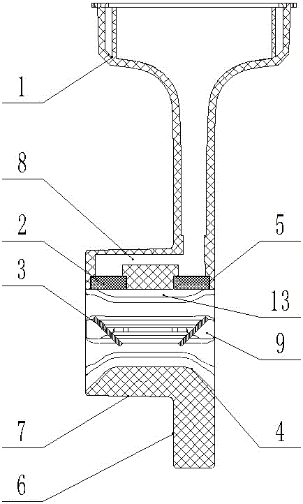
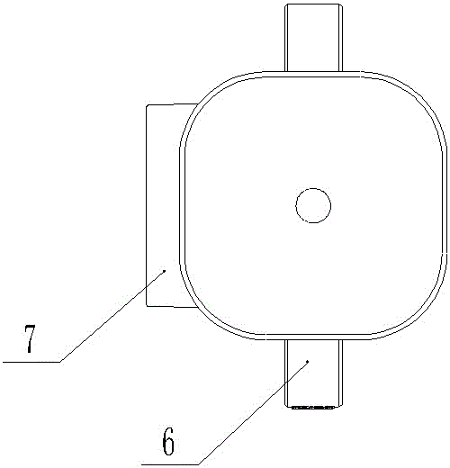
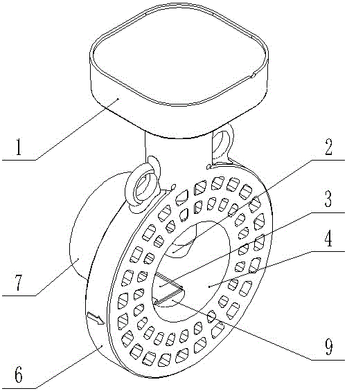
[0068] Embodiment one, with reference to the attached figure 1 , 2 , 3, 4, 5. The measuring pipe section is composed of the wafer body 6 and the guide beam tube 7. The guide beam tube is arranged on one side of the wafer body instead of being symmetrically or asymmetrically arranged on both sides of the wafer body. At the same time, sensors are arranged on the guide beam tube The installation hole 5 , the ultrasonic sensor is arranged in the sensor installation hole; a reflector is arranged in the guide beam tube, and the reflector 3 matches the ultrasonic sensor 2 .

[0069] In this embodiment, the clip body 6 and the guide beam tube 7 are an integral structure, and two reflectors are arranged in the guide beam tube 7, and the reflector is composed of a reflective surface and a support frame, and the reflective surface is arranged on the support frame. The support frame is clamped on the positioning installation slot 9 of the inner pipe section wall of the guide beam tube, ...

Embodiment 2

[0073] Embodiment two, with reference to attached Image 6 , 7 , the measuring pipe section is composed of the wafer body 6 and the guide beam tube 7, the guide beam tube is arranged on both sides of the wafer body, asymmetrically arranged, the length of the guide beam tube exposed on both sides of the wafer body 6 is not equal, and the exposed The long side mainly plays the role of diversion and water diversion, and the exposed shorter side mainly plays the role of fixing the limit gasket; at the same time, a sensor installation hole is arranged on the guide beam tube, and the ultrasonic sensor is arranged in the sensor installation hole 5; the guide A reflector 3 is arranged inside the beam tube, and the reflector matches the ultrasonic sensor.

[0074] Exposing the shorter side is a raised positioning platform 14, which mainly plays the role of fixing the spacer gasket, and its height does not exceed the height of the gasket.

[0075] In this embodiment, the clip body 6 a...

Embodiment 3

[0076] Embodiment three, with reference to the attached Figure 8 , 9 , the measuring pipe section is composed of the wafer body 6 and the guide beam tube 7, the guide beam tube is arranged on one side of the wafer body instead of being symmetrically or asymmetrically arranged on both sides of the wafer body, and at the same time, the guide beam tube is provided with The sensor installation hole, the ultrasonic sensor is arranged in the sensor installation hole 5 .

[0077] A reflector 3 is arranged on the tube wall inside the guiding beam tube, the reflector matches the ultrasonic sensor, and the measurement is completed after reflection.


PUM


Abstract

The invention relates to a supersonic measuring sensor for a water meter, a heat meter and a flowmeter and a using method of the sensor, and belongs to the field of acoustic and sensing technologies. A measuring tube segment is composed of a butt clamp body (6) and a guiding beam pipe (7), the guiding beam pipe is arranged at one side of the butt clamp body instead of being arranged at the two sides of the butt clamp body symmetrically or asymmetrically, a sensor installation hole (5) is arranged in the guiding beam pipe, and the supersonic sensor is arranged in the sensor installation hole (5); and the guiding beam pipe is internally provided with a reflector which matches the supersonic sensor. According to the invention, the guiding beam pipe is arranged at one side of the butt clamp body, so that the difficulty in onsite installation is reduced greatly, and an instrument is protected effectively against damage in the installation process; and the measuring tube segment is free of a flange connecting piece, so that the appearance and structure are simple, the installation size is small, no movable parts are included, a dead lock preventive mechanism is not needed, and the measuring sensor can be widely applied to supersonic liquid metering in the water meter, the heat meter and the flowmeter.

Description

technical field [0001] The invention relates to a measurement sensor for ultrasonic water meter, heat meter and flow meter and its use method, especially a flow meter for measuring liquid (gas) flow or liquid heat in a pipeline by using ultrasonic detection technology, which belongs to the field of acoustics and sensing technology . Background technique [0002] At present, the measurement of the liquid flow or heat in the existing pipeline is to install the ultrasonic sensor in the measuring pipe section, and measure the liquid flow or heat in the pipeline through ultrasonic detection technology; the installation form of the ultrasonic water meter, heat meter and flow meter measurement sensor is mainly There are two types: flange connection form and clip-on form. During the use of these two installation forms, the measurement sensor has the following problems: the measurement sensor installed in the flange connection form, because it involves the operation space of the flan...

Claims


Application Information

Patent Timeline
Patent Type & Authority Applications(China)
IPC IPC(8): G01F1/66
CPCG01F1/66G01F1/662G01F15/16G01K17/00
Inventor 张力新
Owner HUIZHONG INSTR
Why Eureka
Try Eureka