Design method for sliding mode disturbance observer used for servo system control

A disturbance observer and servo system technology, applied in control systems, DC motor speed/torque control, electrical components, etc., can solve problems such as large gain chattering, meet the requirements of reducing modeling accuracy and improve robustness and anti-interference ability, reducing the effect of jitter problems

Inactive Publication Date: 2016-11-02
HARBIN INST OF TECH
View PDF5 Cites 32 Cited by
  • Summary
  • Abstract
  • Description
  • Claims
  • Application Information

AI Technical Summary

Problems solved by technology

However, if the sliding mode variable structure is used to control the servo system with large friction, the sign function will have a high gain and cause a large chattering phenomenon. Therefore, the friction factor must be considered when designing the sliding mode controller.

Method used


Image

  • Design method for sliding mode disturbance observer used for servo system control
  • Design method for sliding mode disturbance observer used for servo system control
  • Design method for sliding mode disturbance observer used for servo system control

Examples


Embodiment 1

[0041] A design method for a sliding mode disturbance observer for servo system control, the steps are as follows:

[0042] 1. Design of sliding mode controller

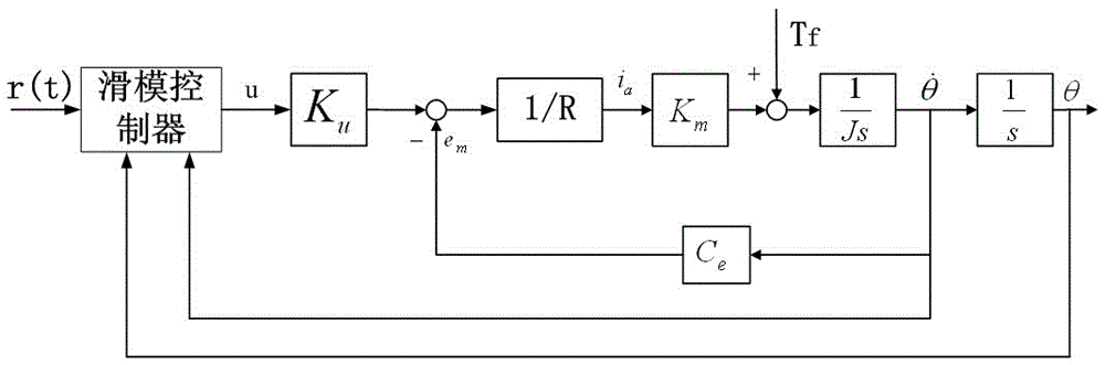
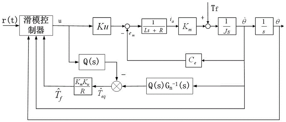
[0043] like figure 1 It means that a sliding mode controller is used to control a servo system affected by friction. First, the state equation of the servo system is established as shown in equation (1):

[0044]

[0045] where r(t) is the command signal, u is the control input, C e is the back EMF coefficient of the motor, K u is the amplification factor of the PWM drive, R is the armature resistance, K m is the moment coefficient, J is the moment of inertia, T f Indicates the frictional disturbance torque. state variable x 1 represents the angle of rotation, x 2 Indicates rotational speed.

[0046] The tracking errors of angular position and angular velocity are respectively

[0047] e=r-x 1 (2)

[0048]

[0049] Design switching function

[0050]

[0051] Exponential Reach Law

[0052]

...

Embodiment 2

[0070] Known parameters of the controlled motor servo system: R=14.7Ω, K m =1.134N m / A, C e =0.119V / (r / min), J=1.79*10 -6 kg*m 2 , K u = 12.

[0071] The transfer function of the motor is

[0072]

[0073] Select the parameter τ=0.001ms of the low-pass filter Q(s), then

[0074]

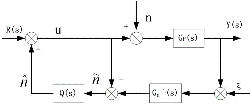
[0075] Then according to Q(s) and G p (s), construct a disturbance observer to get the estimated value of friction torque Select c=30, k=1, ε=1 as the control parameters to design the control rate u.

[0076]

[0077] Through computer simulink simulation, compare the quality of PID control and sliding mode disturbance observer control.

[0078] First, the double closed-loop PID control of the speed loop and the position loop is used. The rule for selecting PID parameters is: first, regardless of the nonlinear friction part of the motor, the PID coefficients of the speed loop and the position loop are determined in turn by the critical proportionality method, and then the coefficient...


PUM


Abstract

The invention provides a design method for a sliding mode disturbance observer used for servo system control, and aims at the friction interference problem in low speed of a servo system and considers the error and uncertainty problem of system modeling. A common DC motor model is used, and a disturbance observer and sliding model variable structure control are combined so that the sliding mode disturbance observer is designed. Firstly the size of the friction torque is observed by using the disturbance observer, and then a sliding mode controller is designed according to the obtained friction torque. The switching item gain of the sliding mode controller can be reduced through observation of friction torque so that the buffeting phenomenon can be reduced. Suppression of the low speed servo system for dead zone, creeping, self-oscillation and other nonlinear phenomena can be realized through the sliding mode disturbance observer so that the requirements for the modeling precision can be reduced and the method has great robustness.

Description

technical field [0001] The invention relates to a design method of a sliding mode disturbance observer for servo system control. Background technique [0002] In low-speed servo systems, the friction torque has a serious impact on the dynamic performance of the servo system. And it leads to some nonlinear phenomena, such as the dead zone at the zero-crossing point of the speed, the phenomenon of low-speed creep, and self-oscillation of sluggish slip. In order to be able to eliminate these nonlinear phenomena, the friction torque needs to be compensated. At present, there are generally two compensation methods. One is the compensation method based on the friction model, such as the Stribeck model and the LuGre model. The process is to first use the obtained speed and position information to estimate the model parameters, obtain the real-time friction torque, and then add the corresponding compensation value to the controller. In this method, the model parameters need to be...

Claims


Application Information

Patent Timeline
Patent Type & Authority Applications(China)
IPC IPC(8): H02P7/00
CPCH02P7/00
Inventor 王毅柳佳男何朕万树同
Owner HARBIN INST OF TECH
Why Eureka
Try Eureka