Eureka AIR delivers breakthrough ideas for toughest innovation challenges, trusted by R&D personnel around the world.

Combined pedal type rat trap

A rat trapping cage and pedal technology are applied in the field of rat trapping instruments, which can solve the problems of occupying a lot of space, fixed volume, difficult to store and transport, etc., and achieve the effects of reasonable structure, simple processing technology and low cost.

Inactive Publication Date: 2016-11-09
黄立成
View PDF9 Cites 0 Cited by
  • Summary
  • Abstract
  • Description
  • Claims
  • Application Information

AI Technical Summary

Problems solved by technology

[0003] The purpose of the present invention is to provide a combined pedal mousetrap, which overcomes the disadvantages of the existing mousetrap, such as fixed volume, large space occupation, and difficult storage and transportation, and can effectively prevent the captured mice from escaping.

Method used


Image

  • Combined pedal type rat trap
  • Combined pedal type rat trap
  • Combined pedal type rat trap

Examples


Embodiment 1

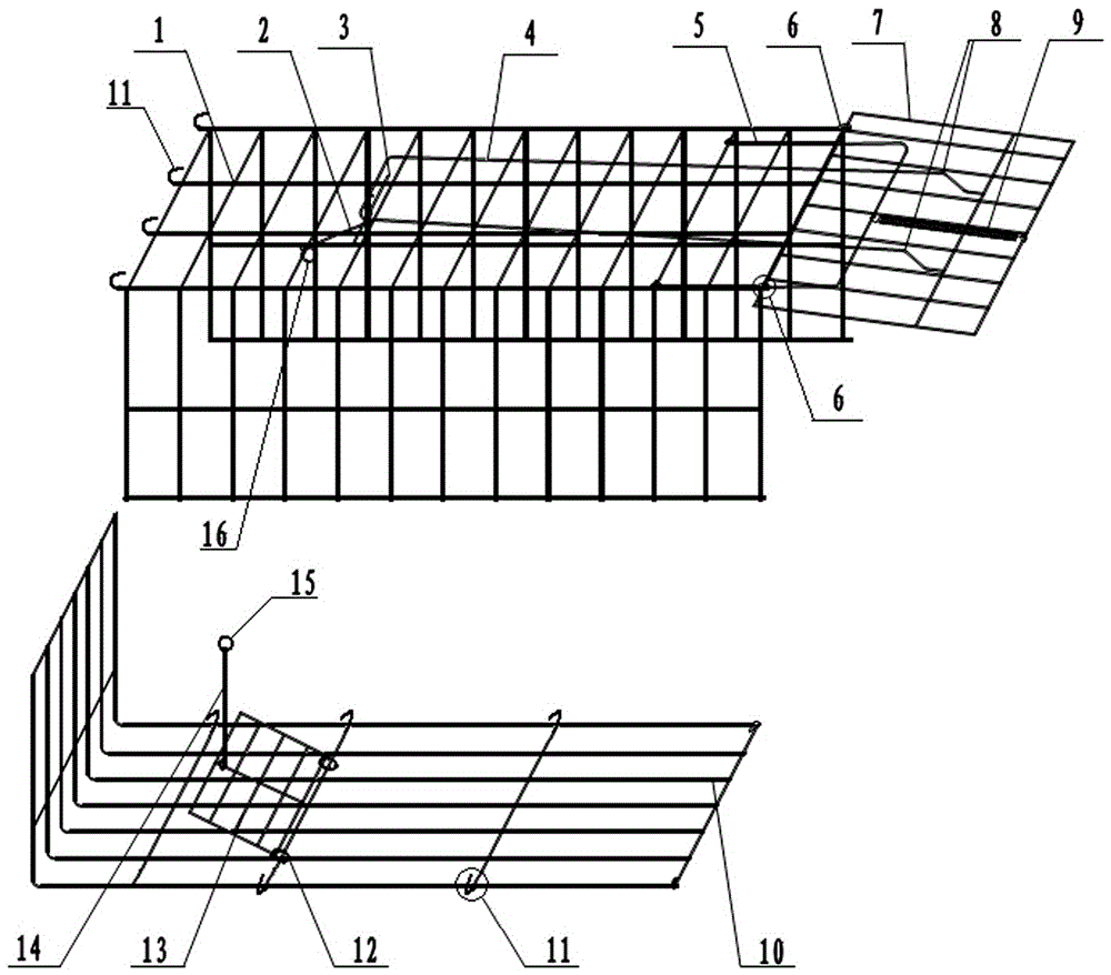
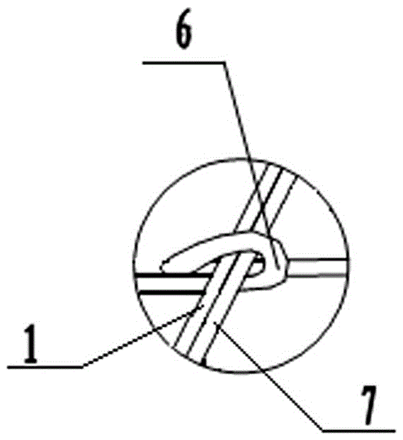
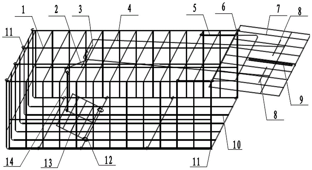
[0021] figure 1 As shown, it is a schematic exploded view of the structure of Embodiment 1 of the present invention. It can be seen from the figure that the cage body is mainly composed of two parts, the upper cage body 1 and the lower cage body 10, and the upper cage body 1 and the lower cage body 10 are detachable Split structure, wherein the upper cage 1 is a U-shaped mesh, and the lower cage 10 is an L-shaped mesh; the upper cage 1 is hinged to the rear upper side of the lower cage 10 through the opening buckle 11 at the rear end of the longitudinal rib, and the lower cage The lower sides of the body 10 are hinged together with the longitudinal ribs on the bottom edge of the cage body 1 through the opening buckles 11 of the transverse ribs. The cage door control device includes a cage door 7, a cage door handle 4, a door control lever 5, an extension spring 9, a trigger lever 2, a trigger shaft 3, a pedal 13 and a suspension rod 14; wherein, the top edge of the cage door 7...

Embodiment 2

[0026] Figure 5 As shown, it is a structural schematic diagram when the cage door is opened in the second embodiment of the present invention. As can be seen from the figure, the structure of the cage body and the cage door is the same as Figure 1~3 The same, in the cage door control device, only the structure of the stop protrusion 8 is the same as Figure 1~3 s difference. Stop projection 8 among the figure is the steel bar on the cage door 7 outsides that two sections are welded fixedly, and its fixed position is the same as figure 1 , 3Corresponding to 4, the working principle is the same, and the state is the same as image 3 Corresponding. At this moment, the stop projection 8 is positioned at the bottom of the door control lever 5 .

[0027] Figure 6 shown, is Figure 5 Schematic diagram of the structure when the middle cage door is closed, the state and Figure 4 Corresponding. At this moment, the stop projection 8 is positioned above the bottom edge of the...


PUM


Abstract

The invention discloses a combined pedal type rat trap which comprises a cage, a cage door and a cage door control device. The combined pedal type rat trap is characterized in that the cage comprises an upper cage body and a lower cage body, the upper cage body and the lower cage body are of detachable split structures and are connected through open buckles of cross bars on the rear sides of longitudinal bars of the upper cage body and open buckles of cross bars on the two sides of the lower cage body; the cage door control device comprises a cage door handle, a tension spring, a door control rod, a trigger rod, a suspended rod and a pedal. According to the rat trap of the structure, the cage bodies are of detachable split structures, so that disassembling and assembling are convenient, no tool is needed during installation, and assembling can be completed in a buckling mode. The upper cage body and the lower cage body can be stacked separately, so that small space is occupied, and remote transportation, storage and selling of the rat cage are convenient. The combined pedal type rat trap is reasonable in structure, low in manufacturing cost, reliable in rat trapping and shutting and capable of making contributions to sanitary and healthy life of people and has popularization value.

Description

technical field [0001] The invention relates to a mouse trap, in particular to a wire mouse trap. Background technique [0002] Rats are one of the four pests, which have brought great distress to people's health and life. There are multiple methods of catching and exterminating mice such as rat poison, sticky mouse board, mousetrap etc. at present, wherein, rat poison is owing to have toxicity, easily causes the mistaken injury of livestock etc., has been phased out gradually. The sticky mouse board only relies on stickiness to catch mice, and it is difficult to catch larger mice, so the effect of catching mice is not good. The most common in the traditional mousetrap is the wire mousetrap cage, and its mousetrap principle is mostly to utilize a dodge door at one end of the cage body and a trigger mechanism to lock the mouse in the cage to catch the mouse. Although the mouse trapping effect of the wire mouse trap is good, there is a big disadvantage, that is, the whole ...

Claims


Application Information

Patent Timeline
IPC IPC(8): A01M23/20
CPCA01M23/20
Inventor 黄立成
Owner 黄立成
Why Eureka
Eureka Blog
Learn More