Vibrational multifunctional stirring device and stirring method thereof

A stirring device and a multi-functional technology, which can be applied to mixers with rotary stirring devices, accessories for mixers, chemical instruments and methods, etc. and discharge, prolong the service life and avoid the effect of damage

Inactive Publication Date: 2016-11-09
WUXI LEHUA AUTOMATION TECH
View PDF9 Cites 2 Cited by
  • Summary
  • Abstract
  • Description
  • Claims
  • Application Information

AI Technical Summary

Problems solved by technology

[0012] For example, the invention patent whose publication number is CN103100345A and the publication date is May 15, 2013, the agitator includes a first blade and a stirring shaft connected to the power output end of the halving device at one end, and the middle part of the first blade is fixedly connected with the other end of the stirring shaft. It also includes a second blade, a sleeve sleeved on the stirring shaft and sliding along the stirring shaft, and a motor fixed on the stirring shaft. The output end of the motor is connected with a telescopic rod for pushing and pulling the sleeve. One end of the second blade is connected to the first The ends of the blades are hinged, and an adjustment rod is hinged between the other end of the second blade and the sleeve; this patent can adjust the stirring position to make the liquid stir evenly, but its blades are short and cannot achieve better stirring. Secondly, the first The number of two blades is also large, the resistance of stirring is increased, and the cost is increased.
[0013] Publication CN10

Method used


Image

  • Vibrational multifunctional stirring device and stirring method thereof

Examples


Embodiment Construction

[0040] The present invention is described in further detail now in conjunction with accompanying drawing. These drawings are all simplified schematic diagrams, which only illustrate the basic structure of the present invention in a schematic manner, so they only show the configurations related to the present invention.

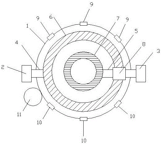
[0041] Such as figure 1As shown, a multifunctional stirring device with vibration includes a mixing bin, a driving component and a stirring component. The stirring component is installed in the mixing bin, and the driving component provides power for the stirring component. The mixing bin is spherical, and the driving component includes Motor Ⅰ and motor Ⅱ, the stirring assembly includes stirring shaft Ⅰ, stirring shaft Ⅱ, stirring blade Ⅰ and stirring blade Ⅱ, stirring shaft Ⅰ and stirring shaft Ⅱ are relatively installed in the mixing chamber, and the axial direction of both is aligned with the mixing The diameters of the bins are coincident, the motor Ⅰ dr...


PUM

PropertyMeasurementUnit
Widthaaaaaaaaaa
Widthaaaaaaaaaa

Abstract

The invention discloses a vibrational multifunctional stirring device and a stirring method thereof. The vibrational multifunctional stirring device comprises a spherical mixing bin, a driving component and a stirring component, the stirring component is installed in the mixing bin, the driving component provides power to the stirring component and comprises a first motor and a second motor, the stirring component comprises a first stirring shaft, a second stirring shaft, a first stirring blade and a second stirring blade, the first motor drives the first stirring shaft, the second motor drives the second stirring shaft, atomizing nozzles and air nozzles are arranged on the mixing bin, a periodical pendulum bob is arranged on the outer wall of the mixing bin, and all the periodical pendulum bob, the atomizing nozzles and the air nozzles are connected with a controller. Compared with the prior art, the vibrational multifunctional stirring device has the advantages that the first motor and the second motor can rotate clockwise or anticlockwise simultaneously, or one rotates clockwise while the other rotates anticlockwise, or one rotates while the other does not rotate, various mixing requirements can be met, stirring is more sufficient, and better stirring effect is achieved.

Description

technical field [0001] The invention relates to a multifunctional stirring device with vibration and a stirring method thereof. Background technique [0002] The stirring device generally consists of a motor, a rotating rod connected to the motor, and a stirring paddle arranged on the rotating rod. The function of the stirring device is to make the liquid and gas medium forced convection and uniform mixing. Most of the stirring devices currently used in industry The devices all have a single structure, and when stirring a liquid medium with a high density, the stirring effect is not good, and the service life of the parts of the stirring device is short. [0003] The purpose of stirring: liquid-liquid mixing, gas-liquid mixing and solid-liquid mixing. The influencing factors of stirring are as follows: [0004] 1) The type, size and rotational speed of the stirrer all have an influence on the distribution of stirring power between bulk flow and turbulent pulsation. [000...

Claims


Application Information

Patent Timeline
IPC IPC(8): B01F7/02B01F15/02B01F15/00
CPCB01F27/191B01F27/62B01F27/60B01F35/12B01F35/712B01F35/7179
Inventor 钱国东
Owner WUXI LEHUA AUTOMATION TECH
Why Eureka
Try Eureka