Drill blade and drill

A drill bit and blade technology, applied in drilling/drilling equipment, drill repair, drilling tool accessories, etc., can solve the problems of reducing the service life of the drill piece, prolonging the cutting time, and increasing the load of the drill piece, so as to save material costs, The effect of reducing processing time and reducing friction

Inactive Publication Date: 2016-11-09
乐清市一线天工具科技有限公司
View PDF13 Cites 0 Cited by
  • Summary
  • Abstract
  • Description
  • Claims
  • Application Information

AI Technical Summary

Problems solved by technology

[0005] During the drilling and cutting process of the above two kinds of inserts, except the main cutting edge at the end is responsible for the main cutting, the secondary cutting edges on both sides mainly play the role of guiding chip discharge, and the secondary cutting edges of the above two kinds of inserts are in the cutting process. The secondary cutting edges on both sides of the center will be rubbed and will become blunt after a long time, thus prolonging the cutting time. Long-term cutting will further cause the secondary cutting edges to become blunt, which will again lead to prolonging the cutting time. This is a vicious circle. , the contact area of ​​the auxiliary cutting edge is larger, so when the drill bit is drilling, the friction force is greater and the resistance is stronger, which not only increases the possibility of the hard and brittle material being drilled, but also increases the load of the drill piece, thereby reducing the Service life of drill bit

Method used


Image

  • Drill blade and drill
  • Drill blade and drill
  • Drill blade and drill

Examples


Embodiment 1

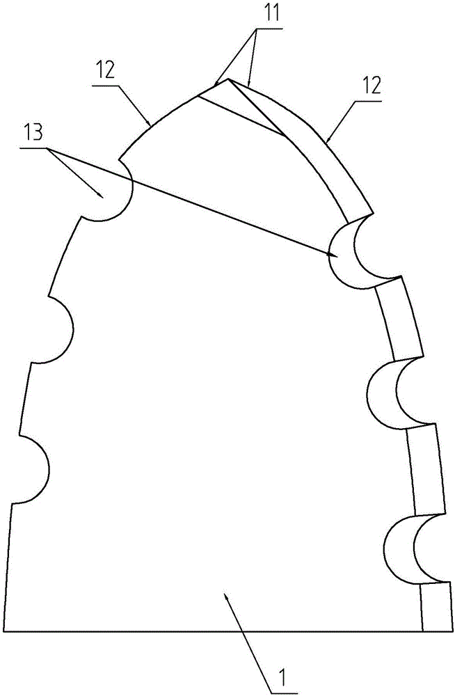
[0035] Embodiment one, with reference to figure 1 As shown, the outer contour of the cutter tooth 1 is arranged in a melon-shaped structure, and the number of secondary cutting edges 12 is two, and the arc-shaped structure of the two secondary cutting edges 12 increases the thickness dimension between the two secondary cutting edges 12, Thereby the structural strength of the secondary cutting edge 12 is enhanced; the two secondary cutting edges 12 are provided with a gap 13 to reduce the contact area of ​​the secondary cutting edge 12 during cutting, and the gap 13 is placed on the two secondary cutting edges 12. There are two on each, and the gaps 13 are distributed on the secondary cutting edge 12 in a complementary manner, so that the cutter tooth 1 is always kept at any depth when drilling, and the secondary cutting edge 12 can guide the chips , so as not to affect the drilling of the main cutting edge 11, but also enable the adjacent minor cutting edge 12 to avoid contact...

Embodiment 2

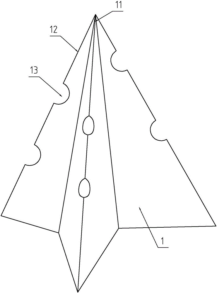
[0036] Embodiment two, refer to figure 2 As shown, the outer contour of the cutter tooth 1 can also be set in a triangular structure, and the number of minor cutting edges 12 is three, and the minor cutting edge 12 is also provided with a gap 13, and the setting of the gap 13 is the same as in the embodiment one by one. Sincerely. It can be seen that the profile of any cutter tooth 1 and the number of cutting edges will reduce the contact area of ​​the cutting edge under the structure of this application, so the specific shape and structure of the cutter tooth 1 and the number of cutting edges do not involve this application the substance of the content.

[0037] In addition, it should be noted that the maximum inner diameter of the relief notch 13 is not less than the thickness of the cutter tooth 1. When the size of the relief notch 13 is properly maintained, it is avoided that the relief notch 13 is too small to easily generate stress concentration and cause the knife to ...


PUM


Abstract

The invention discloses a drill blade and a drill. According to the technical scheme, the drill blade is characterized by comprising a blade tooth, wherein the cross section of the blade tooth is roughly of a triangular structure, a main cutting edge is arranged at the end of the blade tooth, the side edges of the blade tooth are provided with auxiliary cutting edges connected with the main cutting edges, and the side edges of the blade tooth are provided with receding notches relative to the auxiliary cutting edges. The contact area of the auxiliary cutting edges is effectively reduced during cutting, so that drilling resistance is greatly reduced, drilling is easier and faster, and the possibility that hard and brittle materials fracture when drilled is reduced. In addition, since the load on the drill is reduced, the number of times of friction between the drill and a workpiece when a hole is drilled is reduced, and the service life of the drill is remarkably prolonged.

Description

technical field [0001] The invention relates to the technical field of drill bit structure design, more specifically, it relates to a drill bit blade and a drill bit. Background technique [0002] Drill bits generally have a body with an overall basic shape of a cylinder to which inserts are secured at the ends. [0003] At present, the Chinese patent with the notification number CN204262432U discloses a double-sided cutter tooth of a diamond thin-walled drill bit, including triangular notches on both sides of the cutting surface of the cutter tooth, and the upper surface of the cutter tooth is in the shape of a semi-circle, and the welding surface of the cutter tooth is in contact with The area is smaller than the cutting surface. [0004] And, the Chinese patent with the notification number CN101856738A discloses a drill bit and a drill bit, which include a welding base and a cutting edge located at the top of the welding base; a positioning notch is provided in the cente...

Claims


Application Information

Patent Timeline
IPC IPC(8): B23B51/00
CPCB23B51/0027
Inventor 林翔
Owner 乐清市一线天工具科技有限公司
Why Eureka
Try Eureka