
Assembling method of raised floor substructure

An assembly method and box block technology, applied in the direction of assembly machines, metal processing equipment, manufacturing tools, etc., can solve the problems of difficult assembly and low work efficiency, and achieve the effects of reducing assembly difficulty, saving production costs, and shortening the production cycle

Inactive Publication Date: 2016-11-09
BAOJI PETROLEUM MASCH CO LTD +2
View PDF4 Cites 0 Cited by
  • Summary
  • Abstract
  • Description
  • Claims
  • Application Information

AI Technical Summary

Problems solved by technology

[0004] The purpose of the present invention is to provide a method for assembling a box-type base, which solves the difficulty in assembling the box-type base in the prior art due to the ultra-high, ultra-wide, and ultra-fine bonding ratio of the interlayer contact surface. The problem of inefficiency

Method used


Image

  • Assembling method of raised floor substructure
  • Assembling method of raised floor substructure
  • Assembling method of raised floor substructure

Examples


Embodiment Construction

[0023] The present invention will be described in detail below in conjunction with the accompanying drawings and specific embodiments.

[0024] The up, down, left, and right orientations in the following text descriptions are limited to the positions shown in the illustration, and the actual installation positions can be deduced by analogy.

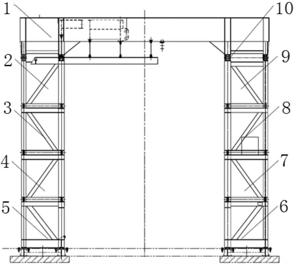
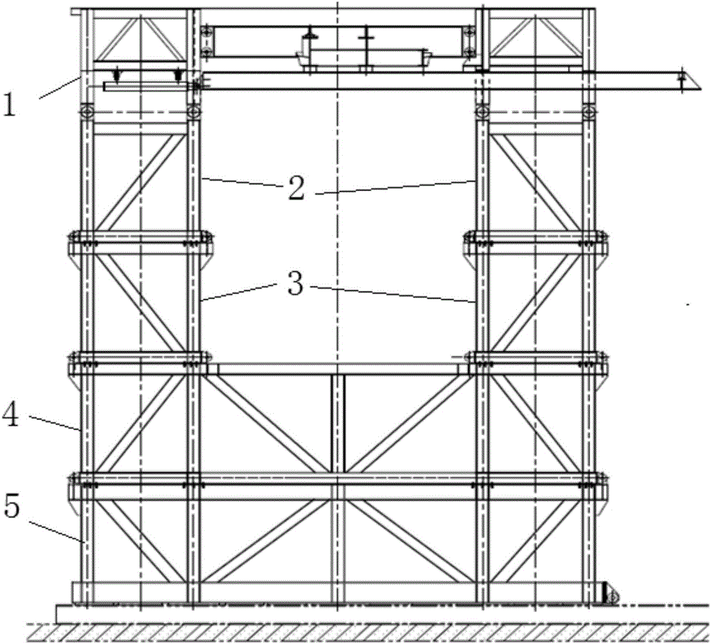
[0025] refer to figure 1 , figure 2 The overall structure of the box-type base to be assembled by the method of the present invention is to include an upper seat 1 of a rectangular frame structure positioned at the top, and the four corners of the lower surface of the upper seat 1 are respectively connected with two left upper supports 2 (i.e. left front upper supports, left rear upper support) and two right upper supports 9 (i.e. right front upper support, right rear upper support), two left upper support 2 lower surfaces are respectively connected with a left middle support 3 (i.e. left front middle support , left rear middle support...


PUM

PropertyMeasurementUnit
Flatnessaaaaaaaaaa
Straightnessaaaaaaaaaa

Abstract

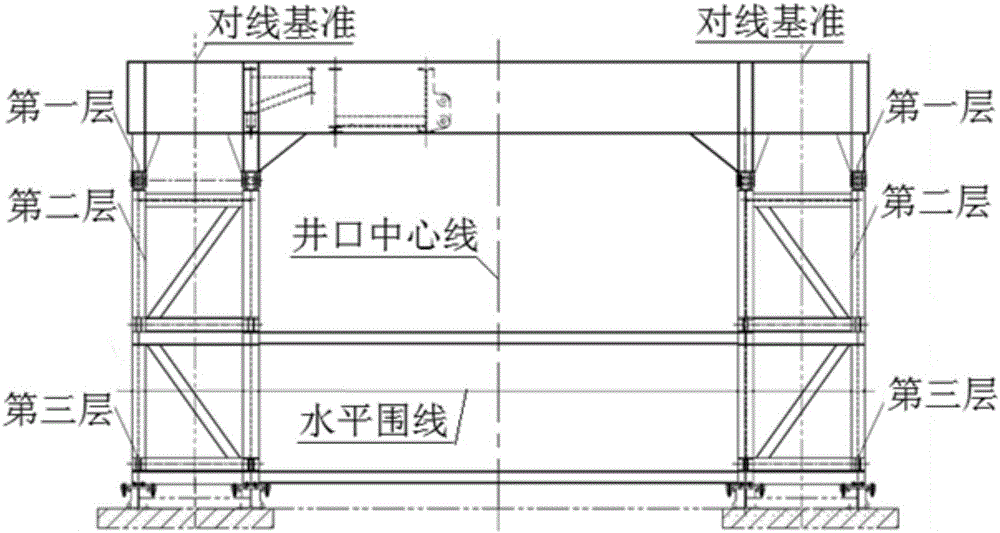
The invention discloses an assembling method of a raised floor substructure, which comprises the following concrete steps: Step 1, laying preparation before assembling, including manufacturing components of different layers, setting layered assembling reference lines and preparing an assembling platform; Step 2, assembling of an upper-layer part, including firmly connecting a first layer, a second layer and a third layer into a whole to form the upper-layer part; Step 3, assembling of a lower-layer part, including firmly connecting the third layer, a fourth layer and a fifth layer into a whole to form the lower-layer part; and Step 4, assembling accomplishment. Through the method provided by the invention, the assembling difficult is reduced, the working efficiency is increased, and the production cost is greatly saved.

Description

technical field [0001] The invention belongs to the technical field of mechanical manufacturing, and relates to a method for assembling a box-type base. Background technique [0002] The box-type base is used to place, support and fix the derrick, drawworks, rotary table and drilling tools of the drilling rig, etc., and bear the self-weight of the above equipment, place the stand, and bear the load of the drilling tool. The layers of the base are positioned by positioning blocks and connected by pins and bolts to form an overall frame structure, which provides an operating place for drilling operations and a space for installing wellhead devices. The base adopts a structure with a high platform and a large space. It is a detachable large module structure and is an important part of the drilling module. Therefore, the production process of the base is particularly important. During the assembly process, it must be strictly set according to the structural characteristics of th...

Claims


Application Information

Patent Timeline
IPC IPC(8): B23P21/00
CPCB23P21/00
Inventor 周丽徐斌荣曹晓宇刘宏亮刘海峰王海峰秦红英
Owner BAOJI PETROLEUM MASCH CO LTD
Learn More