
Stator cramp machining device

A processing device and buckle technology, applied in the field of mechanical processing, can solve problems such as low efficiency and poor processing continuity, and achieve the effect of high process efficiency and high degree of automation

Inactive Publication Date: 2016-11-09
ZHEJIANG OCEAN UNIV
View PDF7 Cites 2 Cited by
  • Summary
  • Abstract
  • Description
  • Claims
  • Application Information

AI Technical Summary

Problems solved by technology

[0003] The stator is usually composed of iron core, coil, skeleton, lead wire, extension spring, etc. The iron core is formed by fastening stator punching pieces through the stator buckle. The stator buckle is usually long and bent along the width direction. It is convenient to press and buckle when tightening the stator punching. At present, the stator buckling is usually formed by punching metal sheets one by one, and the processing continuity is poor, resulting in low efficiency.

Method used


Image

  • Stator cramp machining device
  • Stator cramp machining device
  • Stator cramp machining device

Examples


Embodiment Construction

[0027] The following are specific embodiments of the present invention and in conjunction with the accompanying drawings, the technical solutions of the present invention are further described, but the present invention is not limited to these embodiments.

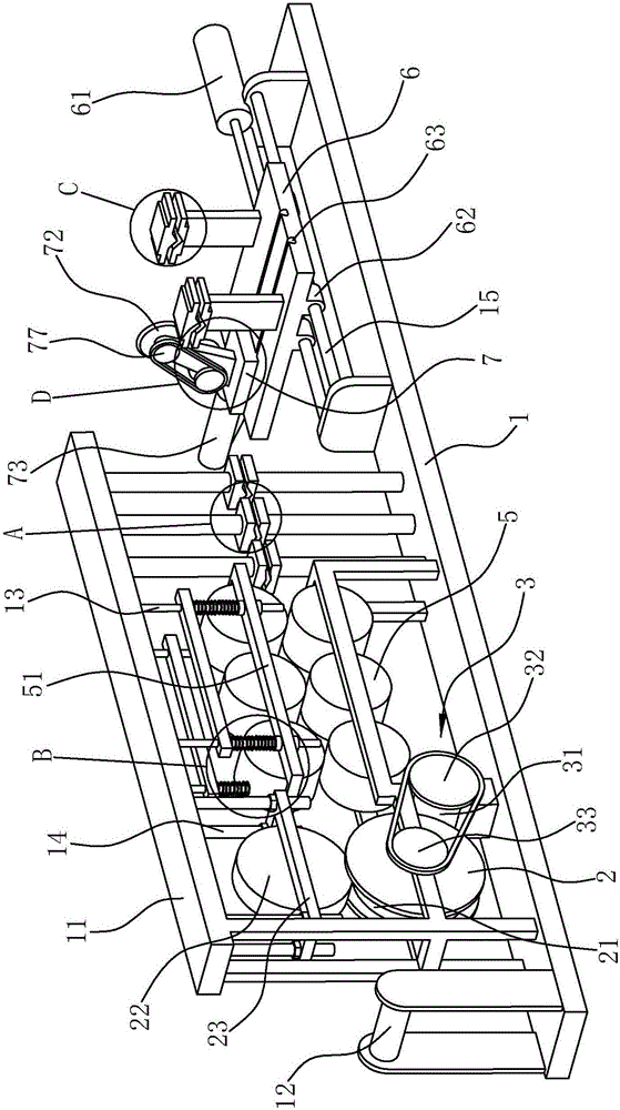
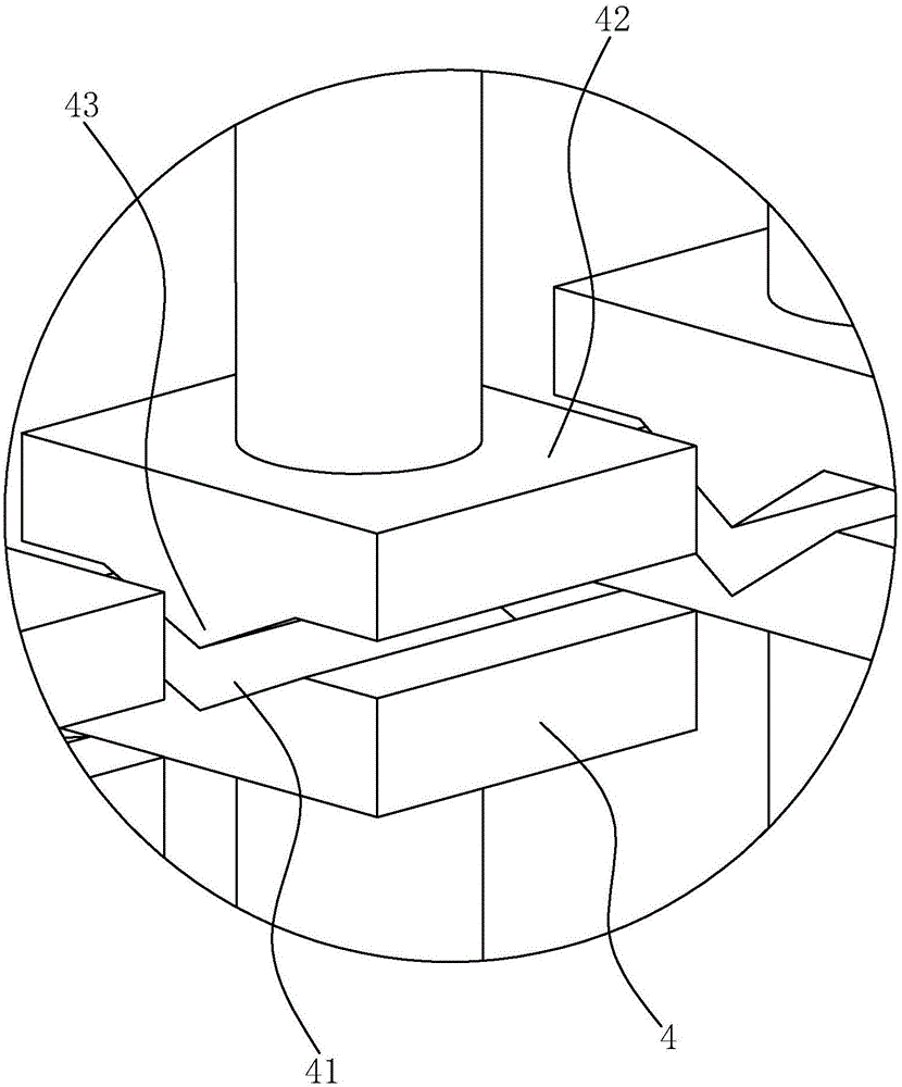
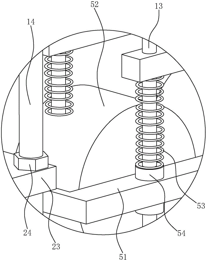
[0028] like Figure 1 to Figure 6 As shown, a stator buckle processing device includes a strip-shaped base 1, which is connected with a frame 11, and the front end of the base 1 is rotatably connected with a positioning shaft 12 for positioning the stainless steel sheet reel. The drive wheel 2 is connected in rotation, and the frame 11 is rotatably connected with a driven wheel 22 that can press the stainless steel sheet on the drive wheel 2 above the drive wheel 2, and the frame 11 is provided with a driving member that can drive the drive wheel 2 to rotate 3. A number of lower mold bases 4 are fixedly connected along the length direction on the base 1, and the upper sides of the lower mold bases 4 are provided with formi...


PUM


Abstract

The invention provides a stator cramp machining device, belongs to the technical field of machining and solves the problem of low efficiency caused by poor machining continuity of a conventional stator cramp. The stator cramp machining device comprises a base, wherein a frame is connected with the base; a driving wheel is rotationally connected with the base; a driven wheel is rotationally connected with the frame and is located above the driving wheel; a plurality of lower die bases are fixedly connected with the base; forming grooves with V-shaped cross sections are formed in the lower die bases; a plurality of upper die bases are fixedly connected with the frame; the upper die bases correspond to the lower die bases one to one; each of the upper die bases is provided with a compression moulding bulge; a longitudinal moving base is connected with the rear end of the frame in a sliding way; a transverse moving base is connected with the longitudinal moving base in a sliding way; and a cutter head is rotationally connected with the transverse moving base. The machining device provided by the invention can automatically finish compression moulding and cutting of the stator cramp, and is high in working efficiency and degree of automation.

Description

technical field [0001] The invention belongs to the technical field of mechanical processing, and relates to a stator buckle processing device. Background technique [0002] The stator is the stationary part of the motor. The stator is composed of three parts: stator core, stator winding and frame. The main function of the stator is to generate a rotating magnetic field, while the main function of the rotor is to be cut by the magnetic force lines in the rotating magnetic field to generate current. [0003] The stator is usually composed of iron core, coil, skeleton, lead wire, extension spring, etc. The iron core is formed by fastening stator punching pieces through the stator buckle. The stator buckle is usually long and bent along the width direction. It is convenient to press and buckle when tightening the stator punching. At present, the stator buckling is usually formed by punching metal sheets one by one, and the processing continuity is poor, resulting in low effic...

Claims


Application Information

Patent Timeline
IPC IPC(8): B23P23/04B21D5/00B21D1/02B21D43/00B21D37/10H02K15/00
CPCB21D1/02B21D5/00B21D5/002B21D37/10B23P23/04H02K15/00
Inventor 杨宗儒郑雄胜
Owner ZHEJIANG OCEAN UNIV
Learn More