

Machining process of thin-wall groove milling stainless steel part
A technology of parts processing and stainless steel, which is applied in the field of thin-wall milling stainless steel parts processing technology, can solve the problems that the thin-wall shielding ring is easy to deform and cannot meet the design requirements, etc., and achieves the effect of low manufacturing cost and convenient operation
- Summary
- Abstract
- Description
- Claims
- Application Information
AI Technical Summary
Problems solved by technology
Method used
Image

Examples
Embodiment 1
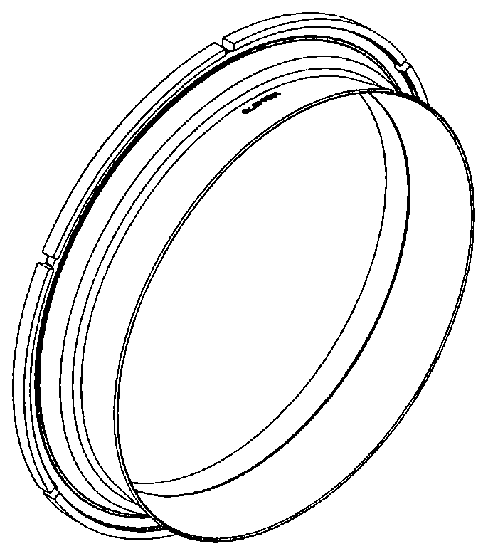
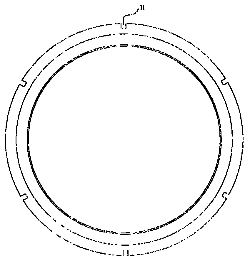
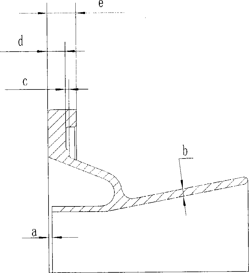
[0029] ANSI310, high-chromium-nickel austenitic stainless steel material is selected, and a thin-walled shielding ring casting blank is first formed and heat-treated. Then, carry out rough machining→natural aging treatment→semi-finishing→rough milling slot→finishing→finish milling slot according to the processing technology described in the present invention, wherein the natural aging treatment is placed for 4 days, and the finally obtained thin-walled shielding ring has a size such as Figure 2 to Figure 5 shown. in, figure 2 is the perspective view of the thin-walled shielding ring, image 3 for figure 2 Front view of a thin-wall shield ring, Figure 4 then figure 2 Right side view of thin wall shield ring. The six notches 11 of the thin-walled shielding ring have a size of 10.414±0.38mm in width and 9.83±0.1mm in depth. Figure 5 for Figure 4 The enlarged view of the dotted line, where a=0.38±0.127mm, b=3.3±0.5mm, c=1.52±0.38mm, d=7.8±0.2mm, e=12.7±0.5mm.
[003...
PUM
 Abstract
Description
Claims
Application Information