
Double-acting tool changing device of numerical control machine tool

A technology of CNC machine tools and tool devices, applied in positioning devices, metal processing mechanical parts, clamping and other directions, can solve the problems of inconvenient production, inconvenience of processes, waste of time and material resources, etc., to ensure usability and speed up tool change. the speed and the effect of reducing wear

Inactive Publication Date: 2016-11-09
张民胜
View PDF9 Cites 0 Cited by
  • Summary
  • Abstract
  • Description
  • Claims
  • Application Information

AI Technical Summary

Problems solved by technology

[0002] In the automatic tool changing device of the CNC milling machine, it is necessary to transfer and load and unload the tool between the tool magazine and the milling machine spindle. In the prior art, a manipulator is used, and the manipulator has a clamping part. Put the used tool back into the tool magazine, then take out the new tool from the tool magazine, and install the new tool on the milling machine spindle of the milling machine. The difference is that the above two processes cannot be carried out at the same time, and need to be operated one by one. The use of machine tools will waste a lot of time and material resources, which brings great inconvenience to production

Method used


Image

  • Double-acting tool changing device of numerical control machine tool
  • Double-acting tool changing device of numerical control machine tool

Examples


Embodiment Construction

[0014] The following will clearly and completely describe the technical solutions in the embodiments of the present invention with reference to the accompanying drawings in the embodiments of the present invention. Obviously, the described embodiments are only some, not all, embodiments of the present invention.

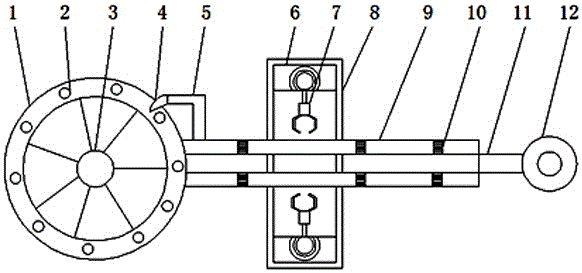
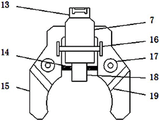
[0015] refer to Figure 1-2 , a double-action tool changing device for a numerically controlled machine tool, comprising a tool magazine 1, a tool clamp 7, a tool holder 8, a tool rail 9 and a chuck handle 15, a tool groove 2 is installed inside the tool magazine 1, and a knife slot 2 is installed inside the tool magazine 1 The tool magazine rotating shaft 3 is installed, and the right side of the tool magazine 1 is equipped with a delivery tool rail 9, and the upper left side of the tool delivery track 9 is equipped with a shifting tool bar 5, and the left side of the tool bar 5 is equipped with a shifting blade 4, and the tool track 9 is sent. An elastic rod 10 is ...


PUM


Abstract

The invention discloses a double-acting tool changing device of a numerical control machine tool. The double-acting tool changing device comprises a tool changer, tool clamps, a tool clamping device, a tool feeding rail and chuck handles. Tool grooves are formed in the tool changer, and a tool changer rotary shaft is installed in the tool changer; the tool feeding rail is installed on the right side of the tool changer, a tool poking rod is installed on the left side of the tool feeding rail, and a tool poking piece is installed on the left side of the tool poking rod; an elastic rod is installed in the tool feeding rail, and the tool clamping device is installed on the surface of the tool feeding rail; a power device is installed in the tool clamping device, and the tool clamps are installed below the power device; fixing buckles are installed on the tool clamps, and the chuck handles are installed below the tool clamps; and tool ejecting plates are installed below the tool clamps, and displacement adjusting rods are installed on the left sides of the tool ejecting plates. The tool poking rod is of a rotatable structure, and the tool poking piece can be rotated at all angles when the tool changing device is used for tool changing; and tools can be conveniently pulled out of the tool grooves, and the rate of tool changing can be increased.

Description

technical field [0001] The invention relates to the technical field of numerical control machine tools, in particular to a double-action tool changing device for numerical control machine tools. Background technique [0002] In the automatic tool changing device of the CNC milling machine, it is necessary to transfer and load and unload the tool between the tool magazine and the milling machine spindle. In the prior art, a manipulator is used, and the manipulator has a clamping part. Put the used tool back into the tool magazine, then take out the new tool from the tool magazine, and install the new tool on the milling machine spindle of the milling machine. The difference is that the above two processes cannot be carried out at the same time, and need to be operated one by one. When the machine tool is in use, a lot of time and material resources will be wasted, which brings great inconvenience to the production. Contents of the invention [0003] The object of the prese...

Claims


Application Information

Patent Timeline
IPC IPC(8): B23Q3/157
CPCB23Q3/1572B23Q3/15726
Inventor 张民胜王祥福
Owner 张民胜
Learn More