
A pneumatic self-generating semi-trailer suspension device

A suspension device, semi-trailer technology, applied in auxiliary drive devices, control devices, suspensions, etc., can solve problems such as hidden dangers of driver's personal safety, easy damage to spring steel plates, damage to leaf springs, etc., so as to ensure personal safety and avoid overloading. , the effect of prolonging the service life

Active Publication Date: 2018-01-16
安徽皖鹏新能源车辆制造有限公司
View PDF5 Cites 0 Cited by
  • Summary
  • Abstract
  • Description
  • Claims
  • Application Information

AI Technical Summary

Problems solved by technology

For a semi-trailer using this suspension method, when some wheels touch the ground and some wheels are suspended, all the loads of the semi-trailer will be borne by the wheels that touch the ground. Axle overload, on the other hand, will reduce the traction of multi-axle drive vehicles, which will easily cause damage to wheels, axles and leaf springs due to exceeding their strength limit
[0003] In the process of driving a semi-trailer, the unevenness of the road will cause the vibration of the vehicle, which will affect the driving comfort and make the car body more vulnerable to damage. Therefore, consider how to convert the energy generated by the vibration into power use, and change the original existence. It is particularly important to turn the problem into a driving force
[0004] At the same time, when the vehicle is running, each steel plate of the leaf spring of the suspension device of the semi-trailer will move up and down, thereby generating friction, and this friction will interact with each other, so that the spring steel plate is easily damaged, thus causing serious damage to the driver. The personal safety of personnel poses a great risk

Method used


Image

  • A pneumatic self-generating semi-trailer suspension device
  • A pneumatic self-generating semi-trailer suspension device
  • A pneumatic self-generating semi-trailer suspension device

Examples

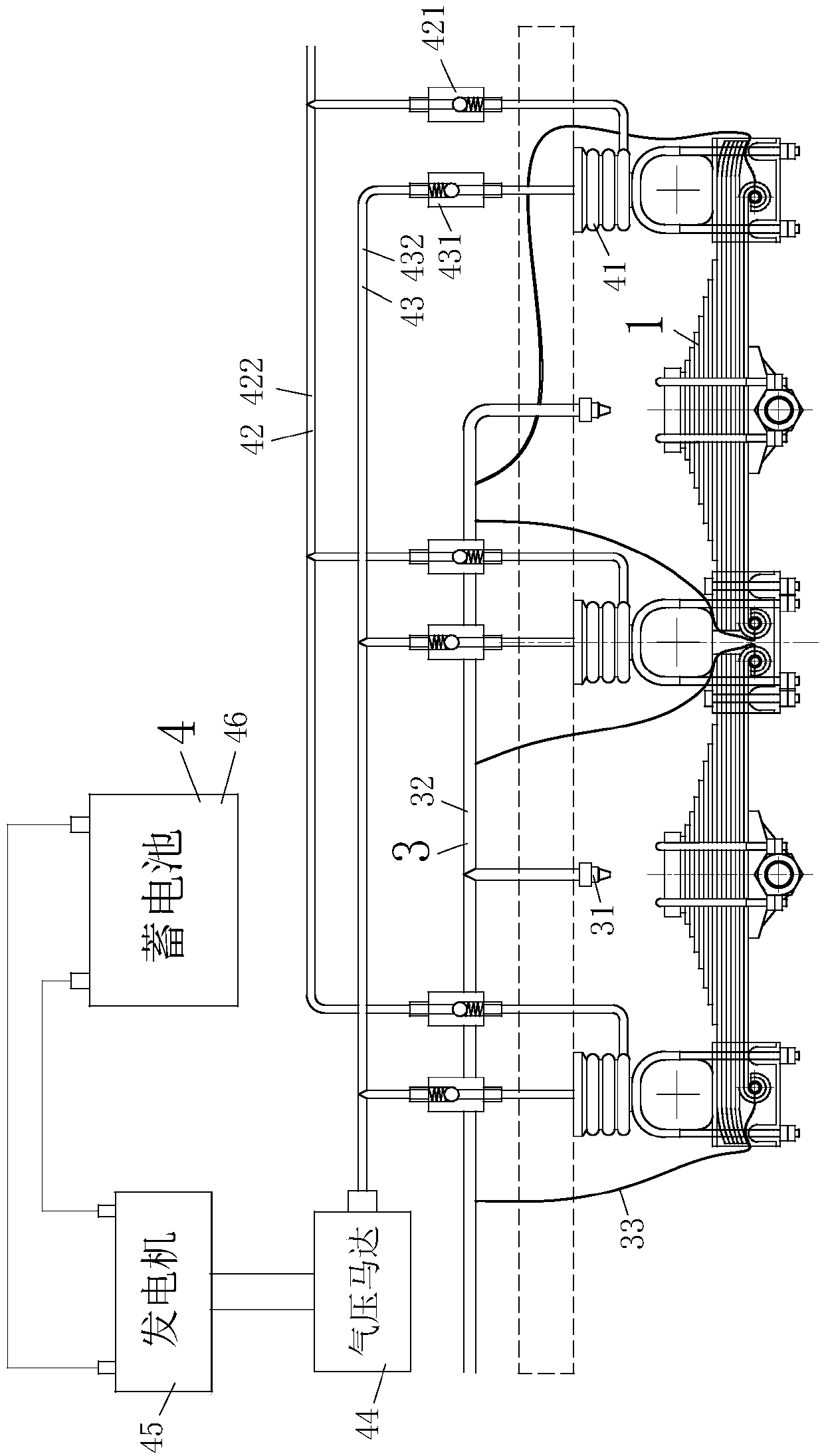
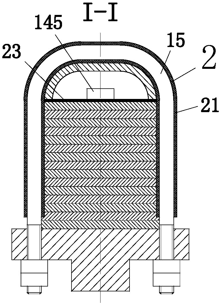

Embodiment Construction

[0026] In order to make the technical means, creative features, goals and effects achieved by the present invention easy to understand, the present invention will be further elaborated below in conjunction with the embodiments.

[0027] Such as figure 1 , figure 2 , image 3 with Figure 4 As shown, a pneumatic self-generating semi-trailer suspension device of the present invention includes a suspension main body 1, a protection main body 2, a cooling main body 3 and a power generation main body 4; the suspension main body 1 includes a suspension bracket 11, an axle 12 , leaf spring support 13, leaf spring 14, U-bolt 15, support seat 16, bearing pin 17 and balance shaft 18.

[0028] The leaf spring 14 includes a front spring 141 and a rear spring 142, the front and rear ends of the front spring 141 and the rear spring 142 are provided with roll ears 143 as pin holes, and each roll ear 143 is provided with There is a liquid inlet hole 144, the number of the suspension brac...


PUM


Abstract

The invention relates to the field of semi-trailers, in particular to a pneumatic self-power-generation type semi-trailer suspension device. The pneumatic self-power-generation type semi-trailer suspension device comprises a suspension body, a protective body, a cooling body and a power generation body. The suspension body comprises a suspension support, an axle, a steel plate spring support, a steel plate spring, a U-shaped bolt, a supporting seat, a pin shaft and a balance shaft. The cooling body comprises a nozzle, a main cooling pipe and a thin cooling pipe. The power generation body comprises an air bag, an air inflow loop, an air outflow loop, a pneumatic motor, a power generator and a storage battery. The protective body comprises a first anti-abrasion anti-slip rubber sleeve, a second anti-abrasion anti-slip rubber sleeve and an anti-abrasion anti-slip rubber cushion. The problem that part of wheels are suspended in air on bumpy road surfaces can be solved, abrasion of the suspension device is retarded, the service life of the suspension device is prolonged, vibration of the axle can be converted into electric energy, and resources are effectively utilized.

Description

technical field [0001] The invention relates to the field of semi-trailers, in particular to a pneumatic self-generating type semi-trailer suspension device. Background technique [0002] The semi-trailer suspension device is one of the main components of the semi-trailer. Its main function is to effectively, reasonably and firmly connect the moving parts of the semi-trailer axle with the semi-trailer beam. The suspension device of the road semi-trailer, the suspension bracket is welded to the lower end of the main longitudinal beam of the semi-trailer, the load on the body is transmitted to the leaf spring through the suspension bracket, and then to the axle; the other side of the axle is connected to an adjacent The leaf spring bracket is connected to bear the lateral force. For a semi-trailer using this suspension method, when some wheels touch the ground and some wheels are suspended, all the loads of the semi-trailer will be borne by the wheels that touch the ground. ...

Claims


Application Information

Patent Timeline
Patent Type & Authority Patents(China)
IPC IPC(8): B60G11/06B60G13/14B60G11/10F03G7/08
CPCB60G11/06B60G11/10B60G13/14B60G2202/112F03G7/08
Inventor 李晓秋
Owner 安徽皖鹏新能源车辆制造有限公司
Learn More