A suction cup conveying device and control method thereof
A conveying device and suction cup technology, used in conveyor control devices, measuring devices, conveyors, etc., can solve the problems of slow speed, poor effect, and inability to realize online detection, and achieve the effect of efficient transportation and accurate image data.
- Summary
- Abstract
- Description
- Claims
- Application Information
AI Technical Summary
Problems solved by technology
Method used
Image
Examples
Embodiment 1
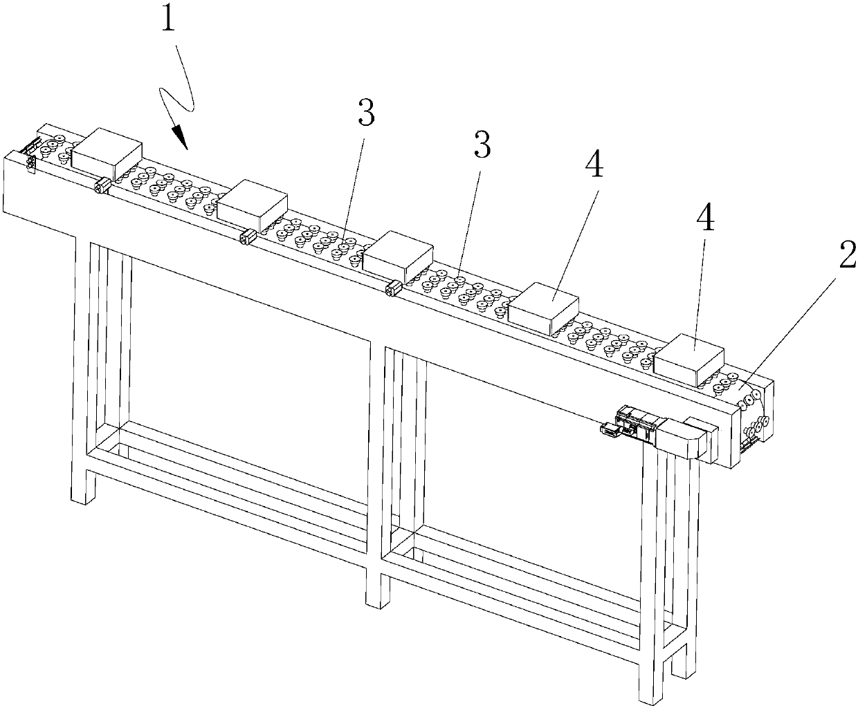
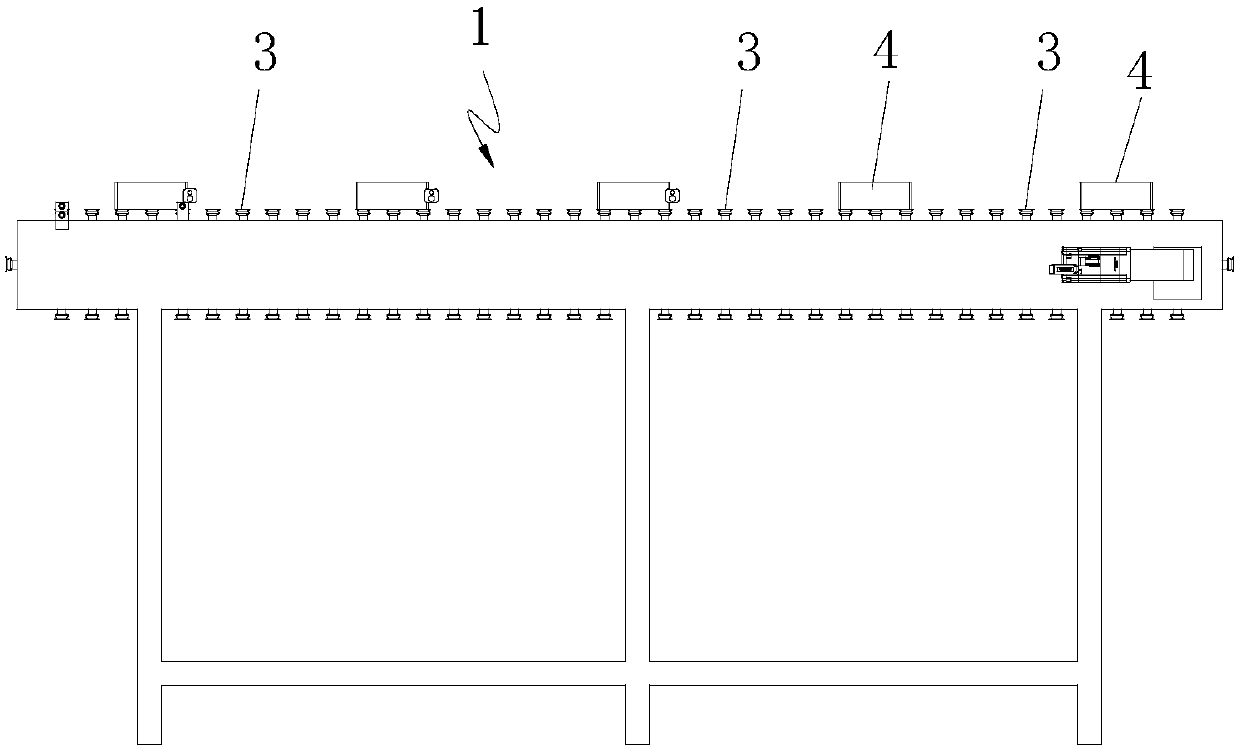
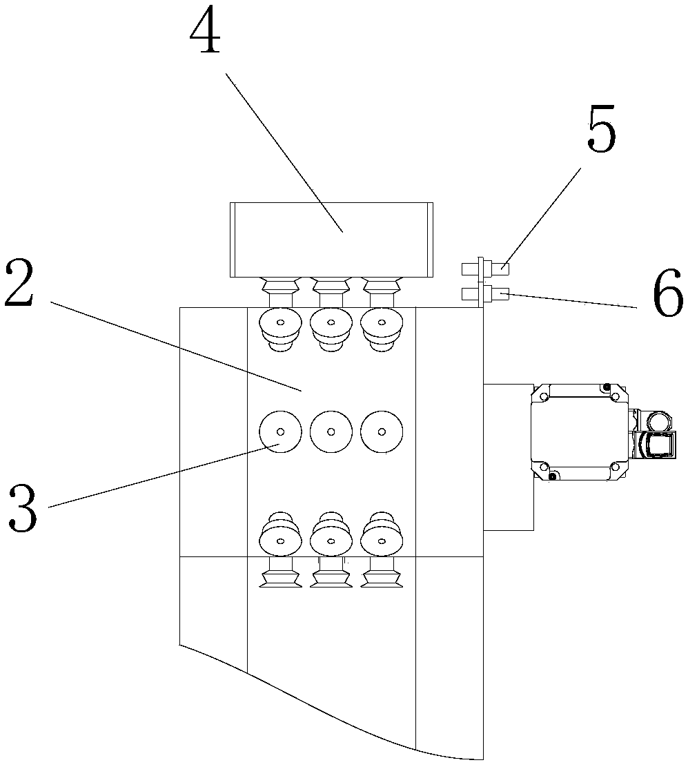
[0053] A sucker transfer device, comprising a sucker transfer mechanism 1 and a control system, the sucker transfer mechanism includes a conveyor belt 2, a solenoid valve and a plurality of suckers 3, the suckers are respectively arranged on the conveyor belt, and there are a plurality of solenoid valves connected to the suckers respectively, Used to control the opening or closing of the suction cup;
[0054] The control system is used to control the solenoid valves so that the suction cup is opened when the workpiece 4 enters and closed when the workpiece is output.
[0055] Preferably, the suction cups protrude from the belt surface of the conveyor belt.
[0056] Preferably, the suction cups are evenly arranged on the conveyor belt in multiple rows, the distance between the suction cups between two rows is equal, and there are multiple solenoid valves, which are respectively connected to each row of suction cups to control the opening or closing of each row of suction cups; ...
Embodiment 2
[0069] The difference between this embodiment and Embodiment 1 is that there are three suction cup transmission mechanisms, the three suction cup transmission mechanisms are respectively connected end to end, and the three suction cup transmission mechanisms are respectively the first suction cup transmission mechanism and the second suction cup transmission mechanism And the third sucker transfer mechanism.
[0070] The inlet of the second sucker transfer mechanism is located above the outlet of the first sucker transfer mechanism, the outlet of the second sucker transfer mechanism is located above the inlet of the third sucker transfer mechanism, and the second sucker transfer mechanism and the third sucker transfer mechanism are arranged in an L shape.
[0071] Working process and principle of work of the present invention: take visual detection as embodiment to illustrate here:
[0072] The workpiece enters the first suction cup transmission mechanism after being output fr...
Embodiment 3
[0076] Preferably, when the conveyor belt inlets of multiple suction cup transmission mechanisms are respectively arranged below one of the suction cup transmission mechanisms and are respectively arranged along its transmission direction, the multiple suction cup transmission mechanisms include an output suction cup transmission mechanism 7 for transmitting workpieces and For transferring each workpiece and distributing each workpiece to each output suction cup transmission mechanism 8, the output suction cup transmission mechanism is arranged below the distribution suction cup transmission mechanism and the conveyor belt inlet of the output suction cup transmission mechanism is respectively along the distribution suction cup transmission mechanism transmission direction set up.
[0077] The working process and working principle of the present invention: after the workpiece is output from the workpiece auxiliary introduction device, it first enters the distribution suction cup...
PUM
 Abstract
Description
Claims
Application Information
 - R&D
- Intellectual Property
- Life Sciences
- Materials
- Tech Scout
- Unparalleled Data Quality
- Higher Quality Content
- 60% Fewer Hallucinations
Browse by: Latest US Patents, China's latest patents, Technical Efficacy Thesaurus, Application Domain, Technology Topic, Popular Technical Reports.
© 2025 PatSnap. All rights reserved.Legal|Privacy policy|Modern Slavery Act Transparency Statement|Sitemap|About US| Contact US: help@patsnap.com


