Double-action safety gear lifting mechanism

A technology of lifting mechanism and safety gear, which is applied in the field of bidirectional safety gear lifting mechanism, can solve the problems of complex structure and high production cost of the lifting mechanism, and achieve the effect of high cost performance, low production cost and simple structure

Inactive Publication Date: 2016-11-09
SHAANXI SIUSAI ELECTROMECHANICAL TECH CO LTD
View PDF5 Cites 4 Cited by
  • Summary
  • Abstract
  • Description
  • Claims
  • Application Information

AI Technical Summary

Problems solved by technology

The existing safety gear lifting mechanism mostly uses the rotation of the shaft to drive the crank to rotate, thereby driving the lifting rod t

Method used


Image

  • Double-action safety gear lifting mechanism
  • Double-action safety gear lifting mechanism
  • Double-action safety gear lifting mechanism

Examples


Embodiment Construction

[0031] The principles and features of the present invention are described below in conjunction with the accompanying drawings, and the examples given are only used to explain the present invention, and are not intended to limit the scope of the present invention.

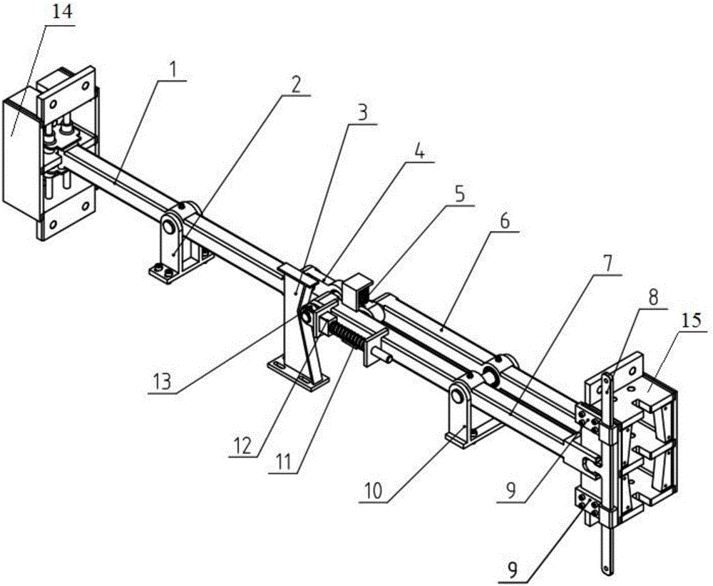
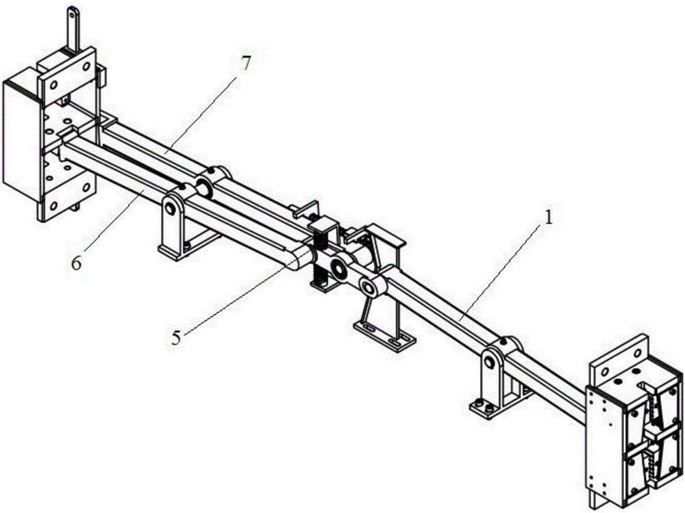
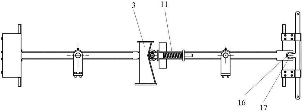
[0032] Such as Figure 1 to Figure 5 As shown, a two-way safety gear lifting mechanism includes a first elevator two-way safety gear 14, a second elevator two-way safety gear 15, a first brake lever 1, a second brake lever 6, a lifting rod 7, and a balance beam 4 and the rope end connecting rod 8; the first elevator two-way safety gear 14 and the second elevator two-way safety gear 15 are left and right symmetrically arranged, and one end of the first brake lever 1 is inserted into the first elevator two-way safety gear 14, and the first brake lever The other end of 1 is rotatably connected to one end of the balance beam 4, one end of the second brake lever 6 is inserted into the second elevator two-way safety gear ...


PUM


Abstract

The invention relates to a double-action safety gear lifting mechanism. The double-action safety gear lifting mechanism comprises a first elevator double-action safety gear, a second elevator double-action safety gear, a first brake rod, a second brake rod, a lifting rod, a balance beam and a rope end connecting rod, wherein the first elevator double-action safety gear and the second elevator double-action safety gear are in left-right symmetry, one end of the first brake rod is inserted into the first elevator double-action safety gear, the other end of the first brake rod is rotatable connection with one end of the balance beam, one end of the second brake rod is inserted into the second elevator double-action safety gear, the other end of the second brake rod is in rotatable connection with the other end of the balance beam, one end of the lifting rod is rotatably connected with the middle of the balance beam, and the other end of the lifting rod is connected with one end, arranged on the lateral side of the second elevator double-action safety gear, of the rope end connecting rod. The double-action safety gear lifting mechanism is simple in structure, low in manufacturing cost and high in cost performance.

Description

technical field [0001] The invention relates to the technical field of elevator operation safety devices, in particular to a bidirectional safety gear lifting mechanism. Background technique [0002] When the elevator runs overspeed, it will trigger the action of the speed limiter. The wire rope of the speed limiter will make the safety gear move through the safety gear pulling mechanism, and the elevator car will stop after the safety gear moves. The existing safety gear lifting mechanism mostly uses the rotation of the shaft to drive the crank to rotate so as to drive the lifting rod to lift up, and the safety gear pulls to stop the car. This kind of lifting mechanism has a complicated structure and high manufacturing cost. Contents of the invention [0003] The technical problem to be solved by the present invention is to provide a bidirectional safety gear lifting mechanism with simple structure, low manufacturing cost and high cost performance. [0004] The technical...

Claims


Application Information

Patent Timeline
IPC IPC(8): B66B5/04B66B5/16
CPCB66B5/044B66B5/16
Inventor 邓健陈庆李军
Owner SHAANXI SIUSAI ELECTROMECHANICAL TECH CO LTD
Why Eureka
Try Eureka