Mask plate assembly, installation method thereof and evaporation device

An installation method and mask technology, which are used in vacuum evaporation plating, devices for coating liquid on surfaces, electrical components, etc., which can solve the problems of evaporation material offset, masking strip 2011 offset and damage, and color mixing.

Active Publication Date: 2016-11-09
BOE TECH GRP CO LTD +1
View PDF6 Cites 43 Cited by
  • Summary
  • Abstract
  • Description
  • Claims
  • Application Information

AI Technical Summary

Problems solved by technology

[0004] like Figure 1a As shown, in the evaporation process, in order to accurately evaporate the evaporation material to the preset position of the evaporation backplane 100, it is necessary to attach the evaporation backplane 100 to the lower mask plate 200, However, when the vapor deposition backplane 100 is bonded to the mask plate 200, since the vapor deposition backplane 100 has a greater gravity than the mask plate 200, the vapor deposition backplane 100 itself has a greater gravity, so that the vapor deposition The sag of the backplane 100 in the direction F close to the mask 200 is larger than the sag of the mask 200 in this direction, so that when the backplane 100 for evaporation and the mask 200 are in contact Afterwards, relative sliding will occur, which in turn will cause the mask plate 200 to shift, thereby causing the position of the evaporated material to be evaporated on the back plate 100 for evaporation to shift.
In addition, if Figure 1b As shown, the effective mask area 201 on the above-mentioned mask plate 200 includes a plurality of shielding strips 2011 arranged at intervals. There will be friction between the board 100 and the shielding strip 2011, under the action of this friction force, it is easy to make the shielding strip 2011 shift and be damaged, and then cause bad phenomena such as color mixing
[0005] To sum up, since the sag of the backplane 100 for evaporation is larger than that of the mask 200, when the backplane 100 for evaporation and the mask 200 are bonded together, the mask 200 and the shielding strip 2011 will Offset occurs, so that the evaporation material cannot be effectively evaporated to the specified position on the back plate 100 for evaporation, thereby reducing the qualified rate of the product

Method used


Image

  • Mask plate assembly, installation method thereof and evaporation device
  • Mask plate assembly, installation method thereof and evaporation device
  • Mask plate assembly, installation method thereof and evaporation device

Examples


Embodiment Construction

[0050] The following will clearly and completely describe the technical solutions in the embodiments of the present invention with reference to the accompanying drawings in the embodiments of the present invention. Obviously, the described embodiments are only some, not all, embodiments of the present invention. Based on the embodiments of the present invention, all other embodiments obtained by persons of ordinary skill in the art without making creative efforts belong to the protection scope of the present invention.

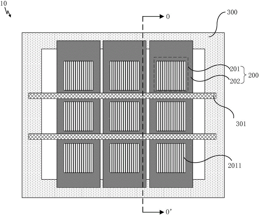
[0051] An embodiment of the present invention provides a mask assembly, such as Figure 2a As shown, the mask assembly 10 includes a support frame 300 and a mask plate 200 fixed on the support frame 300, wherein Figure 2a In the figure, three masks are included as an example for illustration. The reticle 200 includes an effective mask area 201 and an ineffective mask area 202 surrounding the effective mask area 201 .

[0052] In addition, if Figure 2a Sec...


PUM


Abstract

The embodiment of the invention provides a mask plate assembly, an installation method thereof and an evaporation device, and relates to the technical field of display. The offset of the mask plate when a mask plate is attached to a backboard can be reduced, and then the product yield is improved. The mask plate assembly comprises a supporting frame and the mask plate fixed to the supporting frame. The mask plate comprises an effective mask area and an ineffective mask area surrounding the effective mask area. The mask plate assembly further comprises a first supporting strip fixed to the supporting frame. The first supporting strip is arranged on the side, away from the supporting frame, of the mask plate, the projection of the first supporting strip in the plane where the supporting frame is located and the projection of the mask plate in the plane where the supporting frame is located have a first overlapped part, and the first overlapped part is located in the projection area of the ineffective mask area in the plane where the supporting frame is located.

Description

technical field [0001] The invention relates to the field of display technology, in particular to a mask assembly, an installation method thereof, and an evaporation device. Background technique [0002] Organic Light Emitting Diode (OLED) displays have been widely used in computers, mobile phones, etc. Various electronic devices including electronic products. [0003] An OLED display device includes a cathode layer, an organic material functional layer, and an anode layer. The organic material functional layer generally uses a mask to evaporate the evaporation material to a predetermined position on the evaporation backplane by evaporation. [0004] Such as Figure 1a As shown, in the evaporation process, in order to accurately evaporate the evaporation material to the preset position of the evaporation backplane 100, it is necessary to attach the evaporation backplane 100 to the lower mask plate 200, However, when the vapor deposition backplane 100 is bonded to the mask ...

Claims


Application Information

Patent Timeline
Patent Type & Authority Applications(China)
IPC IPC(8): C23C14/04C23C14/24
CPCC23C14/042C23C14/24H01L21/3083H01L21/308B05D1/327B05D1/32H10K71/166B05C21/005
Inventor 林治明王震张健唐富强黄俊杰
Owner BOE TECH GRP CO LTD
Why Eureka
Try Eureka