Manufacturing method of automobile muffler and noise elimination device

An automobile muffler and the technology of its manufacturing method are applied in the direction of mufflers, machines/engines, engine components, etc., which can solve problems such as large noise radiation, and achieve the effects of arc stability, noise reduction, and firm connection

Inactive Publication Date: 2016-11-09
湖南海特汽车部件有限公司
View PDF11 Cites 1 Cited by
  • Summary
  • Abstract
  • Description
  • Claims
  • Application Information

AI Technical Summary

Problems solved by technology

[0007] The technical problem to be solved by the present invention is to propose a muffler that can effectively suppress noise in view of the high-speed airflow that produces large noise radiation when the vehicle exhausts.

Method used


Image

  • Manufacturing method of automobile muffler and noise elimination device
  • Manufacturing method of automobile muffler and noise elimination device
  • Manufacturing method of automobile muffler and noise elimination device

Examples


Embodiment 1

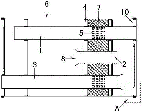
[0033] Such as figure 1 As shown, the muffler includes a shell 6 , an end cover 10 and a core assembly, and the core assembly includes a buffer pipe 2 , an intake buffer pipe 1 , an exhaust buffer pipe 3 and a separator 4 . The buffer pipe 2, the intake buffer pipe 1 and the exhaust buffer pipe 3 are provided with a partition 4 and a sound-absorbing cotton 7, and at the exhaust end of the intake buffer pipe 1 and the exhaust end of the exhaust buffer pipe 3, another A partition 4 is provided. In order to allow the gas discharged from the exhaust hole 5 at the exhaust end of the intake buffer pipe 1 to flow well in the housing 6 , each partition 4 is also provided with an exhaust hole 5 .

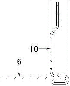
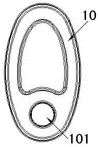
[0034] Such as figure 1 , figure 2 with image 3 As shown, the end caps 10 are installed at both ends of the housing 6, and the end caps 10 are aligned with the edges of the housing 6 and tightly attached, and the edges of the end caps 10 and the housing 6 are clamped and bent for hemmi...

Embodiment 2

[0046] Such as Figure 4 As shown, the muffler includes a shell 6 , an end cover 10 and a core assembly, and the core assembly includes a buffer pipe 2 , an intake buffer pipe 1 , an exhaust buffer pipe 3 and a separator 4 . Weld and fix the buffer pipe plug 9 on the exhaust end of the intake buffer pipe 1, wrap the sound-absorbing cotton 7 on the outside of the buffer pipe 2, the intake buffer pipe 1 and the exhaust buffer pipe 3, and let the sound-absorbing cotton 7 and both sides The partitions 4 are tightly attached so that there is no gap between the sound-absorbing cotton 7 and the partitions 4 on both sides. In order to allow the gas discharged from the exhaust hole 5 at the exhaust end of the intake buffer pipe 1 to flow well in the housing 6 , each partition 4 is also provided with an exhaust hole 5 .

[0047] The buffer pipe 2 is arranged between the intake buffer pipe 1 and the exhaust buffer pipe 3, the middle part of the intake buffer pipe 1 and the exhaust end o...


PUM


Abstract

The invention discloses a manufacturing method of an automobile muffler and a noise elimination device. The manufacturing method comprises the steps of assembling a core assembly; wrapping a buffer tube, an air inlet buffer tube and an exhaust buffer tube between two partition plates of the core assembly with sound absorbing cotton; then, placing the core assembly wrapped with the sound absorbing cotton in an automobile muffler shell; and plugging the two ends of the automobile muffler shell with end covers to form the automobile muffler. The manufacturing method is characterized in that the buffer tube of the muffler is arranged between the air inlet buffer tube and the exhaust buffer tube; the outer sides of the buffer tube, the air inlet buffer tube and the exhaust buffer tube are wrapped with the sound absorbing cotton; and the sound absorbing cotton tightly fits the partition plates on the two sides. According to the manufacturing method, the buffer tube, the air inlet buffer tube and the exhaust buffer tube between the two partition plates of the core assembly are wrapped with the sound absorbing cotton, the two ends of the automobile muffler shell are plugged with the end covers, the automobile muffler is formed, and noise can be suppressed greatly.

Description

technical field [0001] The invention relates to a muffler and a manufacturing method thereof, in particular to an automobile muffler in which a buffer pipe plug is welded and fixed at one end of an intake buffer pipe, and the buffer pipe is arranged between an intake buffer pipe and an exhaust buffer pipe. Background technique [0002] The muffler is a device that prevents sound transmission and allows airflow to pass through, and is an important measure to eliminate aerodynamic noise. When the exhaust gas is discharged from the automobile engine, the pressure of the exhaust gas changes rapidly at the outlet of the exhaust pipe, which generates vibration, and the vibration generates noise. Therefore, the current main method of noise reduction is to install a muffler in the exhaust pipe of the automobile engine. The muffler is used to consume airflow energy and reduce the pressure fluctuation range of the airflow, which can reduce noise. Now, as the requirements of emission ...

Claims


Application Information

Patent Timeline
Patent Type & Authority Applications(China)
IPC IPC(8): F01N1/10
CPCF01N1/082F01N1/10
Inventor 万晶鹏
Owner 湖南海特汽车部件有限公司
Why Eureka
Try Eureka